Search Results:
Search Results:
Search Results:
Search Results:
Find the best emergency stop push buttons here at Sparky Direct. [ Read More ]
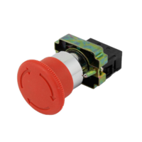
An emergency stop button is a manually operated switching device. Its job is to stop machinery the moment a hazardous situation needs rapid intervention. Most units are red mushroom-head buttons mounted in a yellow surround. The colour combination is the international visual signal for emergency stop, so any operator can find the button under stress.
The button is designed to latch in the tripped position once pressed. It will not release on its own. An operator must rotate, pull, or unlock the head deliberately before the equipment can restart. That mechanical latch is what separates an emergency stop from an ordinary push button.
Pressing the button mechanically opens a set of normally closed contacts in the control circuit. With the contacts open, the control circuit drops out. The coil on the motor contactor loses power, the contactor opens, and the motor stops. The same logic applies to any load wired through the safety circuit.
Because the button latches mechanically, the contacts stay open after the operator lets go. The machine cannot accidentally restart while someone is clearing the hazard. Twisting or pulling the head releases the latch and resets the contacts ready for a deliberate restart by the operator.
Emergency stop buttons provide a fast, reliable way to stop dangerous machinery before a person is seriously injured. They are required by law on machinery and equipment installations under Australian workplace health and safety legislation. A correctly placed and tested e-stop reduces the severity of an accident by disconnecting the hazardous energy source within fractions of a second.
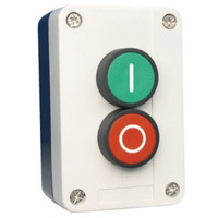
A stop start station wired alongside an e-stop covers the same machine for routine operation. The green start button energises the contactor, the red stop button drops it out for normal shutdown, and the e-stop latches the circuit open in an emergency.
Stop start stations and emergency stop buttons are classified by contact configuration, mounting style, and safety performance level. The contact set determines what the button does in the circuit. The mounting style determines where and how it is installed.
Panel-mount buttons install directly into a control panel, machine enclosure, or wall-mounted box through a 22mm or 30mm hole. They suit purpose-built switchboards and machine cabinets where the actuator sits flush with the door. Sparky Direct stocks individual mechanisms that mount into electrical enclosures on site.
Standalone enclosure-mounted units arrive as a complete station with the buttons already fitted to an IP55 or IP66 box. They are the fastest way to add a remote stop point near a conveyor, pump, or workshop bench. Pull-wire (rope pull) switches extend e-stop coverage along the full length of a conveyor or production line so an operator anywhere along the line can stop it by grabbing the cable.
IEC 62061 and ISO 13849 define safety performance levels (PL) and categories. These determine how reliably a safety function must operate. Higher levels demand redundant contacts, monitoring circuits, and self-checking capability. The performance level required for a machine is set by a risk assessment that weighs the severity of injury against the frequency of exposure and the chance of avoiding the hazard.
The design and construction of emergency stop buttons follows strict international standards. The aim is to make every e-stop reliable, visible, and resistant to accidental operation. The rules cover colour, actuator shape, and reset behaviour.
Emergency stop buttons must be red. The colour separates them from every other control device in a workshop or plant. The surrounding actuator or mounting plate must be yellow to create maximum contrast. A button must also carry the word STOP or an internationally recognised emergency stop symbol so its purpose is unmistakable.
Mushroom-head actuators are the most common design. The large dome gives a big target area for fast activation under pressure. The head must be large enough to press with a hand, a forearm, or even an elbow. At the same time, the actuator must be guarded against accidental activation by tools, falling objects, or careless contact in passing.
An emergency stop button must latch in the pressed position. Letting go of the head must not release it. Release mechanisms include key-release, pull-to-release, and twist-to-release designs. The reset action must be deliberate. A button that resets too easily defeats the purpose of the safety function and lets a machine restart while a hazard is still present.
For machinery used outdoors or in wash-down areas, choose an IP66 rated stop start station. The higher ingress rating keeps dust, hose spray, and weather out of the contacts. Indoor switchroom installations can usually run IP55, which is still well-protected against airborne dust and water from any direction.
Emergency stop buttons must be placed where they can be reached quickly from any spot where a hazard might occur. Bad placement is a common cause of injury even when the buttons themselves are compliant. The aim is to make the button the fastest reaction an operator can take.
Buttons must be within easy reach of every operator working at or near the machine. The reach to the button must not pass through or past the hazardous area. For large machines or long production lines, more than one button is required so every hazardous zone is covered. The result is a network of stop points rather than a single button at the main control panel.
Buttons must be mounted at a height that suits all operators regardless of stature. Australian guidance recommends heights that work for both seated and standing operators. A button hidden behind a stack of pallets or fenced off by other controls is functionally absent. Access must stay clear during every shift, every product changeover, and every cleaning routine.
Conveyors and long production lines need pull-wire switches running their full length. Extra stop stations belong at every operator workstation, every access door, and every loading point. The number and location of stop stations comes out of the machine risk assessment, not a builder's preference. A short rope-pull on a 30 metre conveyor is a compliance failure waiting to be noticed.
An emergency stop button is one element of the machine safety circuit. It only works if the rest of the circuit is designed correctly. The relationship between the e-stop, the contactor, and any safety relays determines whether the stop function survives a single fault.
Emergency stop buttons wire into the safety control circuit in series with other protective devices. When any one button is pressed, the entire safety circuit opens and all hazardous motion stops. The circuit must be designed so that a single fault cannot bypass the stop function. That usually means redundant contacts, monitored wiring, and a contactor that requires positive energisation to run.
The stop circuit feeds the coil of a motor contactor. Drop the coil and the contactor opens, removing power from the motor. For direct online motor starting, a DOL starter combines the contactor, overload, and stop start station in a single assembly.
Safety relays monitor the emergency stop circuit for faults. They look for broken wires, welded contacts, and short circuits across the stop loop. A safety relay that detects a fault locks the machine out until the fault is corrected. Safety programmable logic controllers (PLCs) carry the same function for complex machines with many inputs, many zones, and many actuators.
Emergency stop buttons work alongside light curtains, safety mats, interlocked guards, and gate switches. Every safety device feeds the same safety control circuit, building up multiple layers of protection. The emergency stop is the final manual override. It is the device an operator reaches for when every automatic protection has either failed or was never built for that particular sequence of events.
Australian workplace health and safety legislation places strict requirements on the design, installation, and maintenance of emergency stop systems. These rules cover what must be fitted, how performance is verified, and what records must be kept.
| Standard or Act | What It Covers | Why It Matters |
|---|---|---|
| Work Health and Safety Act 2011 | General duty to provide safe plant and equipment | Sets the legal basis for fitting effective emergency stops |
| AS 4024 Safety of Machinery | Detailed machine safety requirements in Australia | Defines stop function categories and risk assessment method |
| IEC 60947-5-5 | Technical requirements for emergency stop devices | Sets contact performance, durability, and marking rules |
| ISO 13849-1 | Safety-related parts of control systems | Defines performance levels PLa through PLe |
| IEC 62061 | Functional safety of electrical control systems | Defines safety integrity levels SIL 1 through SIL 3 |
A formal risk assessment must set the required safety performance level for the emergency stop system. The assessment weighs the severity of potential injury, the frequency of exposure, and the chance the operator has to avoid the hazard. The output of the assessment dictates the number of buttons, where they go, and what category of contact monitoring the machine needs.
Every emergency stop system needs documentation. That includes design drawings, the risk assessment, and test records. Employers are legally obligated to keep these systems in effective working order. Non-compliance can lead to significant penalties under workplace health and safety legislation, and personal liability can extend to the company officers responsible for plant safety.
Important: Only a licensed electrician should install or modify the wiring of an emergency stop circuit. Incorrect wiring can leave the stop function inoperative without any visible indication. The button may still latch when pressed but fail to stop the machine.
Correct installation and wiring is critical. A stop button that latches mechanically but does not break the circuit is worse than no button at all because it gives a false sense of safety. The wiring must match the design, the design must match the risk assessment, and every connection must be verified before the machine returns to service.
Emergency stop contacts wire in series in the safety control circuit. Any button in the series can stop the machine. Wiring must be protected from mechanical impact, heat, and chemical exposure. Every connection must be tight and secure. Intermittent faults in the stop circuit are particularly dangerous because they can disappear during testing and reappear during an emergency.
Emergency stop cables route separately from power cables. The aim is to keep induced voltage and physical damage off the safety circuit. Routing through conduit, cable tray, or other mechanical protection is essential anywhere damage is possible. Cable colours and labelling follow Australian wiring standards so the safety circuit can be identified during fault-finding without guessing.
For larger installations, mount the stop start station inside a properly sealed surface mount enclosure on the machine frame. Pair the e-stop with a key-operated IP66 isolator switch at the supply. The isolator lets the machine be locked off for maintenance work.
Every emergency stop circuit must be tested and verified before the machine goes into service. Testing confirms that pressing any button stops all hazardous motion within the required time. The result is recorded as evidence of compliance. Verification then repeats at intervals set by the maintenance schedule and after any change to the safety circuit.
Emergency stop buttons need regular inspection, testing, and maintenance to stay functional. The mechanical parts wear, the contacts age, and dust and moisture can build up inside the head. A documented routine catches faults before they become accidents.
Inspect buttons regularly for physical damage, corrosion, and contamination that could impair operation. Check that the actuator moves freely and latches correctly when pressed. Confirm that the reset mechanism requires a deliberate action. A button that resets on its own has lost its safety function and needs immediate replacement.
Test each emergency stop button at set intervals. Press the button, confirm the machine stops immediately, and verify that the machine cannot restart until the button is reset deliberately. Document every test and keep the records. The frequency comes from the machine risk assessment, but monthly is common for plant in daily use and weekly suits high-risk equipment.
Buttons that are physically damaged, corroded, or fail to latch correctly need immediate replacement. Do not attempt to repair a faulty emergency stop button. Any modification can compromise its safety function in ways that are not visible from outside. Replacement parts must match the original in contact configuration and safety performance level so the design assumptions hold true.
Keep at least one spare stop start station and one spare e-stop head on site for every machine that runs in production. A broken e-stop is a stop-the-line event, not a schedule-it-for-next-week event. Same-day replacement keeps a workshop compliant and prevents the temptation to bypass the safety circuit just to get a job out the door.
Troubleshooting emergency stop faults needs a systematic approach. The aim is to identify and clear the fault without compromising machine safety in the process. Three patterns appear over and over in service work.
A button that does not stop the machine when pressed indicates a wiring fault, a faulty contact block, or an incorrect circuit design. Take the machine out of service immediately. Do not run it again until the fault is found and corrected. A licensed electrician or qualified safety engineer should investigate. Common causes include a missing series link, a contact block fitted upside down, and a control circuit bridged across the stop loop during a previous repair.
If the machine will not restart after the button is reset, check for other safety devices that may still be activated. Open guard switches, tripped overloads, and active light curtains all hold the safety circuit open. Inspect the safety relay or safety PLC for fault indications that need clearing first. A persistent failure to restart often points to a wiring fault or a failed safety relay rather than the button itself.
Spontaneous activation of an e-stop signals a wiring fault, a damaged contact, or a mechanical failure inside the actuator. Investigate promptly. The same fault that drops the circuit now may fail to drop it during an emergency. Do not bypass or disable the button to keep the machine running. Bypassing the stop function is a serious workplace safety breach and exposes the operator to risks the original design was meant to control.
Emergency stop technology continues to evolve. Modern devices offer improved monitoring, diagnostics, and integration with plant-wide control systems. The fundamentals stay the same, but the supporting electronics give operators and maintenance teams much earlier warning of trouble.
Modern safety relays continuously monitor emergency stop contacts for open circuits and welded contacts. The fault detection blocks restart if the circuit is not functioning correctly. Continuous monitoring greatly reduces the risk of an undetected fault sitting in the safety circuit until it is needed and found wanting.
Safety PLCs allow detailed monitoring and control of complex multi-axis machines and production lines. Real-time diagnostics let maintenance teams identify and resolve faults before they affect production. Integration with plant-wide safety systems supports coordinated emergency stopping of multiple interconnected machines, so one e-stop can drop a whole cell in a coordinated sequence.
Wireless emergency stop systems remove long cable runs on large machines and production lines. Radio-frequency systems provide reliable communication between the stop button and the safety control circuit. Wireless solutions must meet the same safety performance level requirements as wired systems, and they need careful validation before service. Future revisions of AS 4024 are expected to address collaborative robots and autonomous systems that present new e-stop challenges. Sparky Direct stocks industrial controls from NHP Electrical, Sprecher + Schuh, Clipsal, CABAC, and Connected Switchgear that work with both traditional and modern monitored circuits.
Watch NLS 30876 | Emergency Stop & Start Push Button Control Box IP55 | Grey video
Watch STOPSTART PB5-M215 | Stop Start Station 1 N/O 1 N/C Contacts video
Watch Emergency Stop Button 40mm Twist to Release | SB-BOX | XAL-J174H29 video

The switch was exactly what I needed. It arrived very quickly for rural NSW. I have bought from Sparky Direct before and I will again. I am very pleased with the quality, price and speed of dispatch.
Great low cost but high quality weather proof start/stop station. NO start NC stop all in a robust easy to use Clipsal base.
This is a sensibly-priced emergency switch from Sparky Direct that meets the needs for a seldom used emergency breaker.
Quality products in stock • Fast Australia-wide delivery • Competitive trade pricing
Browse Stop Start Stations & E-Stops → Get Expert Advice →Yes, they are designed to be pressed quickly without precise movement.
Sparky Direct supplies emergency stop buttons Australia-wide, offering reliable and compliant safety control solutions with convenient delivery.
They are securely packaged and delivered via standard courier services.
Unused products are generally eligible for return as long as they are in original packaging and condition, in line with Sparky Direct's Return Policy.
Warranty coverage varies by manufacturer and typically covers defects in materials or workmanship.
Yes, emergency stop buttons are typically sold as individual control devices.
Yes, correct placement ensures fast access in an emergency.
Yes, they are widely used in workshops, factories, and plants.
Yes, they are positioned for easy access and visibility.
Yes, regular testing helps ensure correct operation when needed.
Many models are designed for dusty, wet, or industrial conditions.
Yes, rapid shutdown can reduce the severity of incidents.
Yes, they are a standard safety component in many installations.
Emergency stop buttons are safety control devices designed to immediately stop machinery or equipment in an emergency situation.
Yes, they are typically red with a prominent mushroom head for quick recognition.
They allow operators to stop machinery instantly if something goes wrong.
Yes, they provide a fast and reliable way to stop equipment during emergencies.
Yes, they are specifically designed for industrial and commercial applications.
Yes, they are available in mushroom-head, push-button, and keyed reset designs.
Yes, most emergency stop buttons latch in the activated position until manually reset.
When pressed, they immediately interrupt the control circuit to stop the equipment or process.
Many types of machinery require emergency stop buttons as part of workplace safety and compliance requirements.
They are commonly installed on machinery, control panels, production lines, and industrial equipment.
Quality emergency stop buttons are manufactured to meet relevant AS/NZS electrical and safety standards when installed correctly.
They are used to quickly isolate power to machinery or processes to reduce the risk of injury or equipment damage.