Search Results:
Search Results:
Search Results:
Search Results:
An insulated busbar is a single conductor profile that runs across the top or bottom terminals of a row of devices in a switchboard. Pins or forks engage each device terminal, and the insulating jacket isolates the live metal from adjacent components and the enclosure. One busbar can feed up to 24 modules, depending on the form factor.
Bare copper bars carry current well but require careful clearance, shrouding, and field-applied insulation. An insulated busbar arrives ready to fit. The conductor is sized for a defined current, the pitch matches DIN-rail device spacing, and the jacket is tested for dielectric strength at the factory.
Traditional loop wiring uses short lengths of cable cut, stripped, and torqued into each terminal in turn. A 12-pole single-phase board can demand 22 connections at the active and neutral terminals alone. An insulated busbar collapses into two factory-pressed engagements.
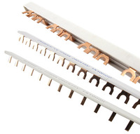
Three formats dominate Australian switchboards: rigid combs for residential and light commercial boards, flexible laminated bars for compact assemblies, and full busbar trunking for industrial distribution. Each fits a different load range and physical envelope.
Rigid combs are the workhorse format for distribution boards. They run from 4 to 24 poles and carry 80 to 100 amps in single-phase pin or fork patterns. The Clipsal MAX9 system, the Resi MAX range, and the Hager KDN family all sit in this group, available through Clipsal and Hager stockholdings.
Laminated busbars stack thin copper sheets between dielectric layers. The result is a low-inductance conductor that flexes around bends in tight enclosures. They suit MCC compartments, drives, and battery storage racks where rigid bars cannot route cleanly.
Trunking systems carry feeders rather than final subcircuits. A prefabricated metal duct houses three or four conductors, with tap-off boxes at intervals for plug-in loads. BTS is common in factories, data halls, and high-rise risers where ratings reach several thousand amps.
The dielectric layer is what separates an insulated busbar from a bare bar. Three main insulation strategies cover residential combs through to industrial trunking, and each has its own thermal and mechanical trade-offs.
Industrial bars often carry an epoxy or fluidised-bed powder coating fused directly to the copper. The coating bonds at high temperature, withstands vibration, and tolerates sustained operation up to 130°C. It cannot be repaired in the field, so damaged sections are replaced.
Heat-shrink tubing is applied over a bar after fabrication, then heated to grip the conductor. It is favoured for retrofit work and short jumpers. The sleeve resists oil and chemicals, but coverage at terminations depends on installer technique.
Laminated bars sandwich Mylar, Nomex, or epoxy film between layers of copper. The construction lowers loop inductance and supports parallel current paths, which matters for fast switching in inverters and UPS systems.
Switchboard designers move to insulated busbars for three measured gains: lower distribution losses, smaller arc-flash incident energy at the device row, and tighter thermal control inside the enclosure.
Resistive losses scale with conductor length and cross-section. A continuous busbar removes the strip-and-loop joints found in cabled boards, cutting joint resistance to near zero. Over a 10-year service life on a 100A board, the energy saving is meaningful for any commercial site.
Insulation cuts the chance of phase-to-phase or phase-to-earth contact during live work. Combined with shrouding on main switches and neutral links, the busbar contributes to a board layout that meets current safe-isolation guidance.
A copper busbar dissipates heat through its full surface and the surrounding air gap inside the enclosure. Cable bundles trap heat, so the carrying capacity of each conductor is derated. For the same enclosure volume, a busbar carries more current at a lower steady-state temperature.
Insulated busbars appear in every sector where compact, repeatable distribution matters. The same product family supports a 6-pole residential board and a 24-pole rooftop solar combiner.
Motor control centres and main distribution boards use rigid copper bars across the chassis, then insulated combs at the device row. The format is faster to terminate than parallel cables and easier to inspect during scheduled maintenance.
Solar combiners and battery enclosures rely on busbars to bring multiple string inputs together at one DC busbar. The MAXBAR+ kit reviewed below illustrates how a single insulated bar can lock in main switch, solar, and battery feeds in a defined config. Compatible solar circuit breakers mount onto the same DIN rail.
Data halls use overhead BTS to feed rack PDUs and cooling units. Tap-off boxes can be relocated as load grows, without de-energising the whole feeder. This flexibility is hard to achieve with hard-wired cable trays.
EV charging cabinets stack RCBOs at high density. Insulated busbars handle the dense pole count and keep the wiring picture simple for inspection. Many dedicated EV products integrate with the Clipsal MAX9 busbar family already common in residential boards.
Three numbers drive the selection: continuous current rating, conductor material, and insulation class. Get any of these wrong and the board either nuisance-trips on heat or fails inspection.
Specify the busbar to match or exceed the upstream device. An 80A main switch needs an 80A busbar. A 100A main switch demands a 100A bar, even if downstream loads are smaller. Diversity does not apply at the busbar.
Copper carries about 60 per cent more current than aluminium for the same cross-section, with better thermal cycling endurance. Aluminium bars are lighter and cheaper, used mainly in long trunking runs. For switchboard combs, copper is the default.
| Spec | Typical Range | What It Means |
|---|---|---|
| Insulation class | Class B (130°C) to Class H (180°C) | Maximum sustained operating temperature |
| Rated voltage | 415V AC up to 1000V AC | Working voltage between conductors |
| Impulse withstand | 4kV to 8kV | Resistance to switching surges and lightning |
| IP rating (enclosure) | IP4X internal, IP2XC at terminals | Protection against finger and tool contact |
The choice between busbars, multi-core cable, and bare bars is rarely about cost alone. Installation time, fault clearance, and serviceability all weigh on the decision.
Multi-core cable is flexible and routes around obstacles. Busbars are rigid but eliminate field terminations. On a 12-pole single-phase board, a busbar removes 22 cable terminations and 22 torque checks. Time on tools drops sharply.
Bare bars sit deeper in the enclosure with mandatory clearance distances and shroud kits. Insulated bars allow tighter packaging and reduce the risk of accidental contact during live testing. Insulating shrouds remain useful at termination points even on insulated systems.
Three standards govern insulated busbars in Australian boards. AS/NZS 3000, AS/NZS 3439 (now superseded by AS/NZS 61439), and the licensed-electrician requirement set out in state legislation.
The Wiring Rules cover circuit protection, conductor selection, and earthing. Section 2 mandates suitable mechanical protection for live conductors and aligns with the IP requirements that insulated busbars satisfy out of the box.
This standard governs the construction and testing of low-voltage switchgear assemblies. Type-tested busbar systems carry documentation that supports compliance. Mixing components across brands without an assessment can void that type-test status.
All work on the busbar side of the main switch must be performed by a licensed electrician. State regulators verify licences before issuing a Certificate of Compliance. Sparky Direct supplies trade customers and licensed contractors only.
A busbar fitted poorly performs worse than the cabled board it replaced. Mounting, joint torque, and labelling each have a direct effect on reliability.
The busbar must seat fully into every device terminal. Partial engagement raises contact resistance, generates heat, and can melt the insulation around the joint. Always trim the comb on the working bench, never inside the enclosure.
Manufacturer torque values are non-negotiable. Under-torqued joints loosen over thermal cycles. Over-torqued joints crack the insulation or strip the device terminal. A calibrated torque screwdriver is the only acceptable tool.
Three-phase busbars use red, white, and blue jackets in the standard Australian sequence. Mark each pole at the device row so future maintainers can verify phase rotation without removing covers.
Before fitting the busbar, dry-fit every breaker and RCBO to confirm pitch alignment. Devices from different ranges occasionally use slightly different terminal spacing, and one mismatched pole forces the whole comb out of position.
A completed board is not energised until three test stages confirm safe operation: insulation resistance, thermal verification, and a final pre-energisation walk-through.
Use a 500V or 1000V insulation tester to verify that the busbar isolation jacket holds off ground and adjacent phases. AS/NZS 3000 sets the minimum acceptable resistance value. Record the readings on the test sheet.
Once the board is loaded, a thermal scan identifies hot spots before they fail. A laser thermometer or thermal camera will reveal joint heating that an instrument check would miss. Re-torque any joint that runs more than 15°C above ambient.
Confirm that all unused poles are blanked, that end caps are fitted, and that the cover plate seats without compressing the busbar. A multimeter verifies continuity across each device before final closure.
An insulated busbar should outlast the board it sits in, but only if scheduled inspections catch wear before it becomes a fault.
Annual inspection checks for jacket discolouration, surface contamination, and torque drift on accessible joints. A clamp meter reading on each subcircuit helps detect imbalance that may stress one phase of the busbar.
Hot spots come from three sources: loose joints, oversized loads, and contaminated terminals. Address each promptly. Replace any busbar showing carbonisation around a terminal, even if the device itself still functions.
A correctly installed busbar lasts 25 to 30 years in residential service. Commercial boards subject to load changes or modifications often need busbar replacement at 15 to 20 years, usually because the device row is rebuilt for higher capacity.
Trade buyers focus on three things: brand match to the existing board, current rating, and stock availability. Sparky Direct stocks the major Australian brands across the most common pole counts.
Trade-grade busbars are sold through electrical wholesalers. The Sparky Direct site lists pin and fork variants, single-phase and three-phase, with same-day dispatch on stocked items. Brand pages collect the full range, including NHP and Legrand options for industrial work.
Generic busbars from auction sites often lack a verified type-test certificate. They may also use undersized copper masked by thicker insulation. Only buy from a supplier who can name the manufacturer and produce a compliance statement.
Three problems account for most busbar failures in service: overheating, insulation degradation, and connection failure. Each has a clear root cause and a clear fix.
Localised heat usually points to a single under-torqued joint or a device drawing more than its rating. Thermal imaging during normal load identifies the affected pole. Re-terminate after de-energising and verify with a follow-up scan.
Cracking or browning of the jacket means the bar has run too hot for too long. Replace the affected section. Investigate the cause: oversized load, board ventilation failure, or a parallel device fault.
Pin-type contacts can wear over many removal cycles. If a device is removed and refitted often, swap to a fork-type or accept a planned busbar replacement at the next major service.
Safety reminder: Never investigate a hot busbar with the board live. De-energise upstream, lock out, and verify dead before touching any conductor or device terminal.
Watch Clipsal MX9B112 | MAX9 Busbar 1PN 12 modules video
Watch HAGER KDN180A | 12 Pole Single Phase Fork Style Insulated Busbar 80A 16mm² video
Watch Clipsal RMXPH312 | 3 Phase 12 Module Busbar Comb 3P+N | Pin Type video

For under 120$ how could you go wrong? A perfect accessory to your solar installation, why? You install this and it is now your work, not to be touched by the next fly by nighter cowboys. It guarantees your work wont be fiddled with as its config locks in main switch, solar and another solar or battery inv cct. You then wire from the main switch off to their existing bus wiring so you spell out what is your work and what is existing. Awesome for compliance because ot shows you care about your work and best bang for buck as it is well priced. Don't stress about hot joints, this bad boy has got you coverrd.
This is very neat busbar for 3 phase applications specially where space is limited and you want to use many many slim RCBOs in one bar. You can shorten the bar as required. Some modifications (off label) also possible if you want to add additional 3 phase MCBs to the bar. Another version of this bar is available in a unique kit form (MX9K318PP) ideal for residential application where you can neatly integrate ev charging, solar and battery storage. This is a brilliant design that should be incorporated into the meter box of all modern residential electrical wiring.
These are awesome products, very fast to install and neat. Make sure you are careful when you select all parts and breakers, as a different height means it won't connect to the busbar and I found there are a few different sizes available..
Quality products in stock • Fast Australia-wide delivery • Competitive trade pricing
Browse Insulated Busbars → Get Expert Advice →They are usually visible inside switchboards but remain safely insulated.
Busbars are used for various purposes in electrical systems. Some common uses include:
Busbars work by providing a low-resistance path for electrical current flow. They are typically made of highly conductive materials like copper or aluminium. Busbars are designed to efficiently carry and distribute electrical current while minimising power losses. The electrical connections to the busbar are made using suitable connectors or terminal blocks.
Busbars offer several advantages over cables in certain applications:
The ampacity or current-carrying capacity of a busbar depends on various factors, including its material, dimensions, cooling, and application. Busbars can handle a wide range of currents, from several amps in low-power applications to several thousand amps in high-power industrial applications.
Sizing a busbar involves considering the desired current-carrying capacity, temperature rise limitations, and the type of busbar system (e.g., enclosed or open). Proper sizing typically requires consulting electrical standards, and manufacturer guidelines, or working with an electrical engineer to ensure the busbar can handle the expected current without excessive temperature rise.
A busbar is a conductive strip or bar used for distributing electrical power, while a terminal is a connection point for individual wires or cables. Busbars serve as common power distribution points, whereas terminals provide the interface for connecting individual circuits or conductors to the electrical system.
Copper is generally preferred for busbars due to its higher electrical conductivity compared to brass. Copper offers lower resistance, better thermal properties, and higher current-carrying capacity. However, brass may be suitable for certain applications where cost considerations, corrosion resistance, or specific mechanical properties are important factors.
Sparky Direct supplies insulated busbars Australia-wide, offering safe and reliable power distribution solutions with convenient delivery.
Insulated busbars are securely packaged and delivered via standard courier services.
Unused products are generally eligible for return according to the seller’s returns policy.
Warranty coverage varies by manufacturer and typically covers defects in materials or workmanship.
They are typically sold individually.
Yes, correct sizing and rating are essential for safe and reliable operation.
Once installed correctly, they generally require minimal maintenance.
Yes, they are often used when upgrading or modernising electrical panels.
Insulated busbars are electrical distribution components that conduct electricity while being fully or partially covered with an insulating material.
Quality insulated busbars are designed for long service life under normal operating conditions.
They help reduce short-circuit risks caused by accidental contact.
Yes, insulation allows safer handling during installation and maintenance.
Yes, they provide a cleaner and more organised appearance inside switchboards.
Yes, they are commonly specified for modern switchboard and panel designs.
They provide added safety and help reduce the risk of accidental contact.
Yes, insulation enhances safety by reducing exposure to live conductive parts.
Yes, they are available in various lengths, cross-sections, and current ratings.
Yes, they are widely used in commercial and light industrial electrical systems.
Yes, they are commonly used in switchboards and distribution panels.
They are typically made from copper or aluminium conductors with a durable insulating coating.
Yes, they are designed to handle a wide range of current ratings depending on their size and construction.
The insulation helps reduce the risk of accidental contact, short circuits, and electrical faults.
Quality insulated busbars are manufactured to meet relevant AS/NZS electrical and safety standards when installed correctly.
They are used to distribute power safely within switchboards, distribution boards, and electrical panels.