Search Results:
Search Results:
Search Results:
Search Results:
Solder is a fusible metal alloy with a melting point well below the metals it joins. When heated by a soldering iron, the molten alloy wets the work surfaces, draws into the joint by capillary action, and solidifies as a continuous metallic bridge between the conductors.
The solidified alloy creates an electrical and mechanical bond at the same time. Electrons pass through the joint with minimal resistance, and the joint resists vibration and pull-out for the service life of the equipment.
The alloy contains tin, lead or silver, and trace metals. These elements form an intermetallic layer with the copper or brass in the conductor, locking the joint at a molecular level. The bond is far stronger than a simple physical contact.
A correctly formed solder joint stays stable across temperature swings, vibration, and current load. This is why soldered joints remain the standard for permanent terminations in PCBs, control panels, and automotive harnesses.
Soldering produces a connection that mechanical joining methods cannot match for reliability over the long term. The joint is gas-tight, low-resistance, and immune to the loosening that can affect screw terminals after repeated thermal cycling.
Resistance at a soldered joint is measured in milliohms. This minimises voltage drop, reduces heat generation under load, and protects sensitive electronics from signal degradation across the connection.
Because solder melts at modest temperatures, components stay below their failure thresholds during the join process. Heat-sensitive parts such as semiconductors, LEDs, and small capacitors survive the operation when technique is sound.
Soldering is used in PCB assembly, automotive looms, marine wiring, control gear, audio equipment, and field repair work. The technique scales from 0.4 mm fine wire on circuit boards up to heavy battery and earth connections.
Two main families dominate trade work: traditional leaded solder, and modern lead-free formulations. The choice affects melting temperature, joint appearance, regulatory compliance, and ease of use.
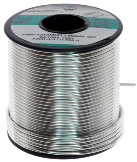
The classic 60/40 tin-lead alloy melts at 188°C and flows easily, producing bright, shiny joints. It remains widely used in repair work, prototyping, and applications outside the consumer electronics RoHS scope. Hamer 60/40 resin-cored solder in 1.6 mm and 3.25 mm gauges is a long-running trade favourite.
Lead-free SAC alloys (Sn-Ag-Cu) melt around 217°C and produce a duller, slightly grainy joint. They are mandatory for new consumer electronics in many jurisdictions under RoHS rules. The higher working temperature requires a hotter iron and closer attention to thermal damage.
Leaded solder is more forgiving for hand work and gives a clearer visual indicator of joint quality. Lead-free is environmentally preferred but demands higher tip temperatures, better flux activity, and more practice to produce consistent results.
| Property | Leaded (60/40 SnPb) | Lead-Free (SAC305) |
|---|---|---|
| Melting point | 188°C | 217°C |
| Joint appearance | Shiny | Dull, grainy |
| RoHS compliant | No | Yes |
| Ease of hand soldering | Easier | Harder |
| Typical iron temp | 320 to 350°C | 360 to 400°C |
Flux removes oxide from the metal surfaces and lets the molten alloy wet the joint. Most electrical solder is supplied as a hollow wire with flux running through the centre, releasing as the wire melts.
Rosin-cored solder is the workhorse of electrical and electronics work. The rosin flux is mildly active when hot and inert when cool, so it leaves no corrosive residue on the joint or the surrounding board.
No-clean formulations leave a small amount of harmless residue that does not need washing off. They suit production environments and field service work where post-solder cleaning is impractical.
Acid-cored solder is intended for plumbing and sheet metal. The acid flux remains corrosive after cooling, attacking copper conductors over time and causing eventual joint failure. It must never be used on wiring or PCBs.
Critical safety point: Acid-cored plumbing solder will destroy electrical connections from the inside. Always confirm the solder spool is labelled as resin-cored or rosin-cored before use on cabling, terminals, or printed circuit boards.
The metallurgy of solder governs how the joint behaves under heat, load, and time. Each alloy has a defined melting profile, mechanical strength, and resistance to fatigue.
Eutectic 63/37 tin-lead has a single melting point of 183°C, transitioning cleanly between solid and liquid. Near-eutectic 60/40 has a small plastic phase between 183°C and 188°C. Lead-free SAC305 melts at 217°C and is also near-eutectic.
Tensile strength of a typical SnPb joint sits around 50 MPa. Lead-free SAC alloys reach 60 to 70 MPa due to the silver content. Real-world joint reliability depends as much on technique and flux activity as raw alloy strength.
Repeated heating and cooling fatigues the alloy at the grain boundaries. Lead-free joints often outlast leaded joints under thermal cycling, which is one reason the electronics industry shifted despite the harder hand-soldering process.
Soldering is one of several termination methods used in electrical work. The right choice depends on conductor size, current rating, vibration exposure, and whether the joint must be reworked later.
Crimping uses a calibrated tool to deform a metal sleeve onto the conductor, forming a gas-tight cold-weld. Crimped joints handle vibration better than solder in some applications, which is why the AS/NZS wiring rules allow either method when carried out correctly. A quality crimping tool is essential for repeatable results.
Welding fuses the parent metals themselves, reaching far higher temperatures. It produces the strongest possible bond but is unsuitable for fine electronics because of the extreme heat involved. Welding suits structural earthing, busbar work, and heavy industrial connections.
Solder offers low resistance and electrical excellence, with a moderate skill barrier. Crimping is fast, repeatable, and tool-dependent. Welding is permanent and structural but specialised. Most trade work uses crimping for heavy gauges and soldering for fine work or repair.
Three factors guide solder selection: alloy chemistry, wire diameter, and the regulatory environment of the finished work.
For repair work and field service, 60/40 leaded solder remains the easiest to use. For new consumer electronics builds bound for sale, lead-free SAC305 is the compliant choice. Match the alloy on the spool to the alloy already on the joint when reworking existing equipment.
Fine 0.5 to 0.8 mm solder suits surface-mount and small through-hole work. General-purpose 1.0 to 1.6 mm covers most terminal and panel wiring. Heavy 2.4 to 3.2 mm rolls are sized for earth straps, lugs, and bus connections.
Check whether the end product falls under RoHS, automotive, or aerospace requirements. Each scheme defines acceptable alloys and may exclude lead-bearing solders entirely. Read the data sheet for activity class, halide content, and operating temperature limits.
Good solder joints depend on cleanliness, heat control, and the correct sequence of contact between iron, work, and solder wire.
Strip insulation cleanly, remove any oxide film from the conductor, and avoid touching the bared metal. Oxide and skin oils block wetting and produce dry, dull joints regardless of how much heat is applied afterwards.
Heat the joint, not the solder wire. Place the iron tip in contact with both conductors, wait one to two seconds, then feed solder into the heated joint. The wire should melt against the work, not the iron tip. Withdraw the solder, then the iron, in that order.
Cold joints look dull or cratered and form when the parts are not fully heated before solder is fed in. Bridging is excess solder spanning two adjacent pads. Both are remedied by cleaning the tip, adding fresh flux, and reflowing the joint properly.
1. Clean and tin the iron tip. 2. Hold both conductors mechanically. 3. Apply iron to the joint for 1 to 2 seconds. 4. Feed solder into the joint, not the tip. 5. Remove solder, then iron, and let the joint cool undisturbed.
Visual inspection catches the majority of defective joints before they reach service. A trained eye reads the joint surface, profile, and fillet shape in seconds.
A correctly formed leaded joint is bright, smooth, and concave with a feathered edge where the solder meets the conductor. Lead-free joints are dimmer but should still show a continuous, well-wetted fillet without voids or cracks.
Cold joints look granular, cratered, or globular, often with a clear demarcation between the solder and the conductor. Disturbed joints show fracture lines from the part moving while the alloy was solidifying. Both should be reworked.
A poor joint adds resistance, generates heat under load, and may fail intermittently. In signal circuits, a cold joint can introduce noise or distortion. In power circuits, the joint can carbonise and start a fire over time.
A correctly soldered joint can outlast the equipment it sits in. Reliability comes from the right alloy, sound technique, and protection from mechanical stress at the termination point.
Solder itself is less conductive than copper, but the intermetallic bond between solder and copper carries the current. Joint resistance is dominated by the bond area, not the bulk solder, which is why a small, well-wetted joint outperforms a large, poorly wetted blob.
Stress relief at the wire entry, such as a strain-relief bend or heat-shrink boot, prevents flex fatigue at the joint. Without it, repeated movement work-hardens the alloy and cracks the connection from the inside.
Temperature swings expand and contract the joint over time. Lead-free SAC alloys handle thermal cycling slightly better than leaded solder, while both benefit from conformal coating in humid or marine environments.
Soldering needs more than just an iron and a roll of wire. A complete kit covers heat delivery, flux application, joint cleanup, and rework capability.
A temperature-controlled iron of 60 to 80 W handles the bulk of trade work. Small fixed-temperature irons suit fine PCB work, and gas-powered torches such as the CABAC butane torch handle large lugs, earth straps, and field jobs without mains power.
Liquid or paste flux supplements the core flux on difficult joints. Solder wick (desoldering braid) lifts excess alloy from pads, and a spring-loaded solder sucker clears through-holes for component replacement.
Keep the iron tip tinned at all times to prevent oxidation. Wipe on a damp sponge or brass wool between joints, and re-tin before storing. A neglected tip transfers poorly and burns out faster, costing more in tips than the maintenance saves.
Soldering crops up across most trade disciplines. Each use case has its own combination of alloy, gauge, and technique.
Fine 0.5 to 0.8 mm solder with no-clean flux suits through-hole and surface-mount rework. A 30 to 40 W temperature-controlled iron protects nearby components while delivering enough heat to wet the pad cleanly.
Vehicle looms see vibration, temperature swings, and moisture. Soldered joints must be backed with adhesive-lined heat shrink tubing or covered with quality electrical tape to prevent strand fatigue and water ingress at the termination.
Mainstream installation work uses crimped lugs and connectors for most terminations. Solder appears on bonded earths, control panel rework, and equipment repair, where the joint must be permanent and low-resistance.
Soldering touches several compliance regimes, from chemical safety on the bench to wiring standards in the finished installation.
The Restriction of Hazardous Substances directive limits lead in electrical and electronic equipment. New consumer products supplied into RoHS jurisdictions must use lead-free solder unless covered by a specific exemption.
Rosin flux fumes irritate the airways. Use fume extraction or work in well-ventilated areas, and wash hands after handling leaded solder. Hot tips reach 350°C and above, so place the iron in a stand whenever it is not in your hand.
IPC-A-610 sets the international acceptability standard for electronic assemblies, defining what good and unacceptable joints look like at three quality classes. AS/NZS 3000:2018 (the Wiring Rules) covers terminations in fixed wiring installations and references soldered joints where used.
Most failed joints come down to a small handful of repeat errors. Recognising them early shortens the learning curve.
Holding the iron too long damages the part long before the joint is finished. If the wire is not flowing within two to three seconds, the issue is usually a dirty tip or insufficient flux, not insufficient heat.
Acid flux on electrical work is the textbook example. Other errors include using inactive R-grade rosin on heavily oxidised joints, or using halide-rich activator flux on circuits that will not be cleaned afterwards.
Too much solder hides joint defects under a blob and can bridge to adjacent pads. Too little leaves a starved joint that cracks under load. The correct amount fills the joint with a smooth concave fillet, no more.
Soldered joints are repairable. Inspection and rework keep equipment in service for years longer than scrap-and-replace cycles.
Look for cracks at the wire entry, dull or whitened surfaces, and any sign of greenish corrosion. Magnification of 10x or higher reveals defects invisible to the naked eye, especially on fine surface-mount work.
Remove old solder with wick or a sucker, clean the pad with isopropyl alcohol, then apply fresh solder with adequate flux. Avoid lifting the pad by limiting iron contact time and supporting the board flat during rework.
Mixing leaded and lead-free solder can produce a brittle alloy with poor reliability. When reworking lead-free assemblies, use lead-free solder. When repairing leaded gear, stick with leaded.
Solder is a long-life consumable. A 500 g roll lasts most independent contractors a year or more, so quality matters more than the lowest spool price.
Sparky Direct stocks trade-grade solder from General Trade Supplies and Hamer alongside other electrical accessories. Online ordering ships nationwide with trade pricing for ABN holders.
Bargain-bin solder often has inconsistent flux fill, off-spec alloy ratios, or contamination that produces dull, brittle joints. Trade-grade rolls from established manufacturers cost a few dollars more and pay back the difference in fewer reworks.
500 g and 1 kg rolls suit working contractors. Larger formats reduce the per-gram cost and cut down on changeovers during big jobs. Stock a fine and a heavy gauge to cover both PCB rework and lug work.
When joints fail or refuse to form, the cause is almost always heat, flux, or contamination. Working through the checklist resolves most field problems.
The most common cause is an oxidised tip or oxidised conductor. Re-tin the tip, add fresh liquid flux, and try again. If the spool is old and the flux core has dried out, switch to fresh stock or supplement with paste flux.
Intermittent faults often trace back to cracked solder joints under thermal or mechanical stress. Reflow the suspect joint with fresh flux, support the wire with strain relief, and retest under load.
Cracks indicate movement during cooling, fatigue from vibration, or thermal shock. Remove the joint, clean both surfaces, and reform with proper support and a longer cooling period before disturbing the connection.
Watch Hamer HSOL60403-25500 | 3.25mm Resin Cored Solder 60/40 | 500g video
Watch Major Tech SL5200 | 1.0mm Multi Core Solder video
Watch SOLDER 3.2 MM THICK 60/40 500GM Roll (Resin Cored) | CSA01508 video

I recently purchased a coil of solder from Sparky Direct. Every time I order from they I get brilliant service and fast postage, also excellent communication. We done Sparky Direct I highly recommended your business to anyone that asks.
Quality products, Great Pricing, Excellent service. I am a purchasing officer for a trailer company and we use sparky direct!
Sn 60 Pb 40 being the most commonly used solder combination flows well in most situations even on slightly oxidised joints
Quality products in stock • Fast Australia-wide delivery • Competitive trade pricing
Browse Electrical Solder → Get Expert Advice →Soldered joints are generally long-lasting when done correctly.
Sparky Direct supplies solder Australia-wide, offering quality electrical solders with convenient delivery.
Solder is securely packaged and delivered via standard courier services.
Unused solder is generally eligible for return according to the seller’s returns policy.
Warranty coverage varies by manufacturer and typically covers defects in materials.
Yes, solder is typically sold in small reels or rolls.
Yes, choosing the correct type ensures safety, performance, and compatibility.
When stored correctly, solder typically has a long usable life.
Yes, it can be stored in a cool, dry place when not in use.
Properly soldered joints are resistant to vibration in many applications.
Yes, fine solder is ideal for precise electronic connections.
Yes, it helps ensure consistent electrical conductivity.
Lead-free solder reduces exposure to hazardous materials and is commonly preferred.
Electrical solder is a metal alloy used to create a conductive and secure joint between electrical components and wires.
Yes, it is widely used by electricians, electronics technicians, and hobbyists.
It creates a strong, reliable, and conductive electrical connection.
Yes, it is commonly used in low-voltage and electronic applications.
Many solders include a flux core to help improve bonding and conductivity.
Yes, solder is available in different thicknesses to suit various applications.
Yes, solder is widely used for electronic components and printed circuit boards.
Solder is commonly used in electrical and electronic repair work when appropriate.
Lead-free solder is a safer alternative made without lead, commonly used to meet modern safety and environmental requirements.
Common types include lead-based solder and lead-free solder.
Quality solders are manufactured to meet relevant safety and material standards suitable for electrical use.
Solder is used for joining wires, terminals, circuit boards, and electronic components.