Search Results:
Search Results:
Search Results:
Search Results:
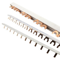
An insulated busbar is a pre-formed conductive link that carries active supply across a row of DIN rail devices in a switchboard. It removes the need for individual cable loops between each circuit breaker, RCBO or main switch, and gives a consistent termination across every device on the row.
Insulated busbars consist of a copper or aluminium conductor enclosed in an insulating sleeve, with conductive pins or forks at a fixed module pitch. The busbar feeds many protection devices from a single active supply point, so one connection at the main switch becomes the supply for every breaker on the row. They are common in residential distribution boards, commercial switchboards, sub-boards and control panels.
Cable links between breakers take time to cut, strip, terminate and dress neatly. A busbar replaces that work with one pre-formed component, which reduces wiring clutter and the number of termination points that could later loosen. Fewer terminations also makes thermal inspections, fault finding and future modifications easier. This does not remove the need for professional installation, torque checks or compliance testing by a licensed electrician.
Insulated busbars appear in domestic switchboards, unit boards, light commercial panels, three phase distribution boards and control panels. They are commonly paired with MCBs, RCDs, RCBOs, main switches, surge protection devices and load control equipment where the device manufacturer confirms compatibility. The choice of busbar is dictated by the device family on the row, not by the board itself.
Pin and fork busbars are not interchangeable. The connection geometry must match the terminal style on the circuit breaker or RCBO, and that compatibility is set by the device manufacturer. Selecting the wrong type is one of the most common and highest-risk purchasing errors with busbars.
A pin busbar uses cylindrical or rectangular pin contacts that insert into the terminal aperture of a compatible device. The terminal screw clamps directly onto the pin. Pin busbars are specified by selected Clipsal and Schneider DIN rail families and by some other manufacturers, but only where the device datasheet calls for pin connection. Before ordering, confirm the model series, pole count, module pitch, current rating and whether end caps are required.
A fork busbar uses two parallel prongs that clamp around a compatible terminal tab or screw terminal arrangement. Fork busbars suit selected Hager, Legrand and other modular device systems where the device terminal is built for fork engagement. Fork alignment and even terminal seating matter for safe contact pressure, so the busbar must sit squarely across every device on the row.
Neither connection type is universally better. The right choice is set by device compatibility, current rating, board layout and the manufacturer documentation for the specific protection devices being linked.
| Feature | Pin Busbar | Fork Busbar |
|---|---|---|
| Connection geometry | Pin inserts into terminal aperture, clamped by terminal screw | Fork prongs clamp around terminal tab or screw terminal |
| Common device families | Selected Clipsal and Schneider DIN rail devices | Selected Hager, Legrand and other modular systems |
| Visual fit | Neat and compact across the row of devices | Sits flat across terminal tabs in compatible boards |
| Compatibility risk | Only suits devices designed for pin engagement | Only suits devices with fork-compatible terminals |
| Best determined by | Device datasheet and manufacturer busbar chart | Device datasheet and manufacturer busbar chart |
Compatibility warning: Forcing the wrong busbar type into a non-matching device creates poor contact, heat build-up at the terminal and non-compliant switchboard work. Always confirm the device manufacturer specifies the busbar type before ordering.
Modular DIN rail devices use a 17.5 mm module pitch, and the busbar pins or forks are positioned to that pitch. Slim RCBOs, compact protection modules and mixed-brand assemblies can break that spacing assumption, so the pins or forks may not line up with every device. Mixing brands or compact RCBO formats in one row is a common cause of misalignment. Check the device datasheet or the manufacturer busbar compatibility chart before purchase.
Once connection type is decided, the next selection step is phase configuration. Electricians match the busbar to the supply arrangement and to the protective devices being linked on the row.
Single phase busbars carry one active conductor across a row of single phase devices. They are the standard choice in domestic and small commercial switchboards. Common pole counts include 6, 12, 18 and 24 modules, depending on the board layout and the device range. Single pole circuit breakers and single pole RCBOs are typical pairings on a single phase busbar row.
Three phase busbars run three active conductors across three phase device positions in the board. They appear in commercial switchboards, workshops, plant rooms and three phase distribution boards. Correct phase sequencing must be maintained, and the protection devices on the row need to be three phase units, such as three pole circuit breakers or three phase RCBOs from compatible device families.
Active busbars carry active conductors, not neutral. They are different to neutral links and neutral bars, which terminate neutral conductors back to the supply neutral. RCBO and RCD-protected circuits require careful neutral routing: each protected circuit must return through the matching device, otherwise the residual current sensing can trip nuisance faults or fail to detect a real fault. When planning a row of RCBOs, the busbar handles active distribution while neutral routing is planned separately, and both must follow the device manufacturer wiring guidance.
Selecting a busbar comes down to a short list of specification checks. Each one must be confirmed against the upstream supply, the protection devices and the enclosure before ordering.
Insulated busbars carry common residential and light commercial current ratings such as 63A, 80A and 100A, with the exact figure set by the product family and conductor cross section. The busbar rating must suit the upstream supply, the main switch and the overall switchboard design. Warm enclosures, outdoor meter boxes and high ambient Australian conditions can require derating, so the busbar should not be selected purely on its nameplate rating.
Pole count is the number of device module positions the busbar covers. Common sizes include 12 pole, 18 pole and 24 pole busbars for residential and light commercial work. For a 12 pole board, choose a busbar that covers the required number of populated device positions and is compatible with the board pitch. Electricians often allow spare poles for future circuits where the enclosure space and supply rating support it.
End caps and shrouds cover exposed conductive busbar ends, including any ends left after the bar is shortened. In many assemblies end caps are required wherever a cut or open end would otherwise expose live metal. Exposed live parts in switchboards must be suitably protected under Australian wiring rules, so the end cap is part of the compliant fit-off, not an optional accessory.
Some manufacturer busbars can be cut to length, but only where the product instructions explicitly permit it. Any cut end must be finished correctly and protected with approved end caps or insulation accessories. Cutting or modifying a busbar must be assessed by a licensed electrician, must not compromise the product rating, and must not affect the switchboard compliance. This page does not provide cutting instructions because the work is electrical work.
Switchboard busbar work involves live components, fixed wiring and protection devices that the building relies on. The work is regulated, and the standards that apply to selection and installation are clear.
Insulated busbars must be selected and installed in accordance with AS/NZS 3000 and the relevant product standards for the busbar and the devices it links. Low-voltage switchboard assemblies are also covered by AS/NZS 61439, which addresses ratings, clearances, short-circuit suitability, insulation and enclosure compatibility. The product ratings on the busbar must be maintained in the finished assembly.
Installing, replacing, cutting or modifying a busbar means working inside a switchboard with live components and fixed wiring. In Australia this is electrical work and must be performed by a licensed electrician. Sparky Direct supplies the products to licensed trades and informed buyers but does not provide DIY switchboard installation guidance. The licensed electrician is responsible for selection, torque, compliance testing and the finished assembly.
The most frequent issues identified during switchboard inspections and electrician feedback include the following recurring patterns.
Buyers often compare insulated busbars against alternative wiring methods or against bare copper busbar arrangements. The terminology around comb busbars also overlaps with pin and fork busbars, which can cause confusion when searching for the right product.
Cable links use short pieces of insulated cable to loop between device terminals. Compared to insulated busbars, cable links take longer to install, are harder to keep neat across multiple devices, and create more termination points to inspect later. Cable links may still be the only option where devices are mixed across incompatible families, where legacy components are involved, or where no compatible busbar exists for the row. Where a compatible busbar is available, it usually wins on installation time, board neatness and thermal reliability.
Bare copper busbars are common in larger switchgear assemblies, where the enclosure provides clearances, restricted access and the assembly verification needed for an exposed conductor. Insulated busbars are preferred in compact DIN rail boards because the sleeve provides touch protection and a neat fit-off in tight spaces. Current rating and assembly verification still drive the selection in both cases, and bare busbars are not a like-for-like swap with insulated comb busbars.
"Comb busbar" is a general shape description: an insulated bar with multiple tooth-like contacts running along it. "Pin" and "fork" describe the actual contact geometry at each tooth. A pin comb busbar has pin contacts; a fork comb busbar has fork contacts. The terms overlap in catalogue language, so when searching for a part, the most reliable filters are the device brand, the pin or fork type and the pole count.
Ordering busbars online works well when the product page lists the device compatibility, pin or fork type, current rating, pole count and module pitch clearly. Sparky Direct lists insulated busbars from multiple manufacturers so the device family and the rest of the switchboard build can be checked against one stock list.
The pre-purchase checks below catch most compatibility issues before a part leaves the warehouse.
Switchboard builders, maintenance contractors and electrical fit-out crews often hold stock of common busbar formats on the van or in the workshop. Bulk ordering helps cover spare ways across multiple jobs, keeps a consistent device range on each board, and avoids the mid-job problem of mixing incompatible bars. Ordering online also lets contractors compare product details, stock availability and dispatch timing before heading to site, which matters when a switchboard upgrade is booked into a tight outage window. Related stock that often goes with busbars includes RCBOs, circuit breakers, main switches and general circuit protection components.
Value on a busbar includes compatibility, compliance, the product rating, manufacturer documentation, stock availability and reduced installation risk. A cheap busbar that does not match the device family on the row is not a saving, because it either cannot be used or creates a non-compliant connection. Uncertified or mismatched imports are a real risk in this category, so reputable Australian electrical suppliers help confirm the product is suitable for the local market and the device range being installed.
Busbars usually have a long service life inside a sealed switchboard, but they do need attention during board upgrades, after fault events or where heat damage is suspected. The decisions below are made by the licensed electrician inspecting the board.
Reuse depends on the busbar condition. The electrician checks for signs of overheating, mechanical damage, terminal deformation, cracked insulation and whether the bar has been previously cut or modified. The manufacturer guidance for that product also determines whether reuse is supported. Damaged, overheated or previously modified busbars are generally replaced rather than reinstalled.
Visible warning signs appear during a board inspection. Each item below means the busbar or its terminations need attention before any further work continues.
Anything on this list calls for the switchboard to be isolated and inspected by a licensed electrician. It should not be opened or probed by anyone untrained.
Switchboard upgrades from MCBs to RCBOs, from older device families to new ranges, or from single phase to three phase often require a new compatible busbar as part of the work. Planning the upgrade includes the new device family, the matching busbar, spare ways for future circuits, board capacity, surge protection and the documentation that the licensed electrician needs to certify the finished assembly. Common upgrade-adjacent products include surge protection devices and updated Clipsal MAX9 and Resi MAX circuit protection components.
Watch Clipsal RMXPH112 | 12 Module Busbar Comb 1P+N | Pin Type video
Watch Hager KDN380A | 12 Pole 3 Phase Fork Style Insulated Busbar 80A 16mm² video
Watch Clipsal MX9B112 | MAX9 Busbar 1PN 12 modules video

This is very neat busbar for 3 phase applications specially where space is limited and you want to use many many slim RCBOs in one bar. You can shorten the bar as required. Some modifications (off label) also possible if you want to add additional 3 phase MCBs to the bar. Another version of this bar is available in a unique kit form (MX9K318PP) ideal for residential application where you can neatly integrate ev charging, solar and battery storage. This is a brilliant design that should be incorporated into the meter box of all modern residential electrical wiring.
Real time saver when used with the single phase CBs/RCBOs and provides good contact for an easy reliable installation
These are awesome products, very fast to install and neat. Make sure you are careful when you select all parts and breakers, as a different height means it won't connect to the busbar and I found there are a few different sizes available..
Quality products in stock • Fast Australia-wide delivery • Competitive trade pricing
Browse Insulated Busbars → Get Expert Advice →