Search Results:
Search Results:
Search Results:
Search Results:
In Australian electrical systems, contactors address a specific operational requirement. They enable control of high-current circuits using low-current signals. Separating the control voltage from the load voltage creates flexibility for automation, remote operation, and enhanced personnel safety.
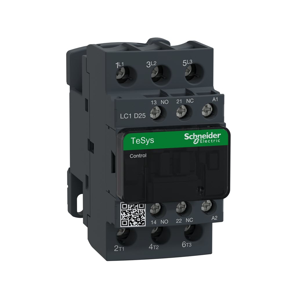
A contactor operates through electromagnetic principles. When voltage energises the coil, magnetic flux pulls a movable armature toward a fixed core. This mechanical movement forces contact surfaces together, completing the circuit path to downstream equipment.
Manual switching requires direct operator access. Contactors eliminate this constraint. The electromagnetic mechanism enables activation from control panels, programmable logic controllers, time clocks, or building management platforms. Typical control voltages range from 24V to 240V, well below the switched load levels that may reach several hundred amperes.
Specifications include rated current capacity, number of poles, coil operating voltage, load category designation, and operational life expectancy. Proper selection requires matching these parameters to installation conditions and Australian regulatory standards.
Mechanical switches demand physical proximity for operation. Electrically controlled contactors remove this limitation, enabling switching from distant locations or automated sequences triggered by external conditions.
This capability matters in facilities where loads cycle according to schedules, environmental sensors, or production sequences. Building automation, industrial process control, and scheduled equipment operation all depend on contactors rather than manual intervention.
All work on fixed installations and switchboard equipment falls under licensed electrician requirements per Australian regulations.
Both devices use electromagnetic coils to operate contacts. The difference appears in current handling and construction robustness. Relays typically manage control signals and lighter loads. Contactors handle substantial current levels with appropriate arc management and contact durability.
Contactor design includes heavier contact materials, enhanced arc suppression, and load-specific duty ratings. Additional auxiliary contacts often provide status feedback or enable circuit interlocking for safety purposes.
Small signal applications suit relay technology. Motor starting, high-current lighting control, and heavy industrial loads require contactor-grade equipment.
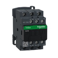
Contactor selection begins with understanding the available types. These are classified by current type, pole arrangement, mounting configuration, and intended load category.
Alternating current contactors predominate in Australian commercial and industrial installations. Standard voltages include 230V single-phase and 400V three-phase supply systems. Applications span motor control, HVAC equipment, lighting control, and heating systems.
Load matching is critical. A unit rated for resistive heating may fail prematurely on motor duty. Lighting contactors require different specifications than capacitor switching applications. Verification against manufacturer load tables prevents misapplication.
Direct current presents a specific challenge. AC waveforms cross zero voltage twice per cycle, naturally interrupting arc formation. DC maintains constant polarity, allowing arcs to sustain without intervention.
DC contactors incorporate enhanced arc control measures including extended gap distances, magnetic arc deflection, and specialised contact alloys. These features enable safe circuit interruption in battery systems, solar installations, EV infrastructure, and industrial DC applications.
Applying an AC contactor to DC loads creates serious hazards including contact fusion, inability to clear the circuit, thermal damage, and potential fire risk. Always verify DC ratings when specifying equipment for direct current systems.
Pole count determines the number of independent circuits switched simultaneously. Single and double-pole units serve particular single-phase requirements. Three-pole contactors suit three-phase motor and equipment loads. Four-pole configurations address applications requiring neutral switching or specialised control schemes.
Circuit design dictates appropriate pole count and must comply with AS/NZS 3000 requirements. Licensed electricians verify pole configuration against equipment specifications and installation conditions.
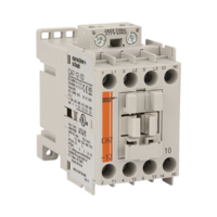
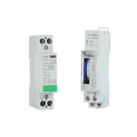
Standard 35mm DIN rail mounting enables organised switchboard and control panel layouts. These contactors offer compact dimensions, accessible terminals, straightforward labelling, and simplified maintenance access.
Electricians, panel fabricators, and service contractors utilise DIN rail equipment in lighting panels, pump control assemblies, HVAC boards, and automation systems. Proper enclosure selection, adequate protection devices, clear identification, and compliant installation remain mandatory.
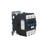
Higher current ratings, enhanced construction, and extended operational life characterise heavy-duty contactors. These units handle large motors, industrial compressors, heavy pumps, manufacturing equipment, and high-frequency switching cycles.
Selection based solely on purchase cost often leads to premature failure. Undersized contactors or inappropriate duty ratings fail when subjected to actual load conditions. Proper specification requires confirmed load data and manufacturer compliance verification.
AC and DC contactors serve distinct purposes and cannot be substituted. Each addresses the specific electrical behaviour of its respective current type.
Alternating current naturally aids arc extinction. Each zero crossing provides an opportunity for the arc to clear as voltage drops to zero and reverses polarity. This characteristic simplifies arc management in AC contactors.
Direct current maintains steady voltage and polarity. Without natural zero crossings, arcs persist until actively extinguished through mechanical means. DC contactors employ wider contact spacing, magnetic arc manipulation, cooling chambers, and purpose-designed contact materials.
Attempting to switch DC loads with AC contactors produces contact welding, failed interruption, excessive heat generation, and significant fire hazard. Equipment must carry appropriate DC ratings for the actual application.
Standard Australian power systems operate at 230V single-phase and 400V three-phase AC. Contactors for these systems control motors, lighting circuits, HVAC loads, heating elements, and general commercial equipment. Available formats range from compact DIN rail units through heavy industrial frames, supporting single through four-pole configurations.
Battery installations, solar power systems, electric vehicle charging infrastructure, DC control circuits, and specialised industrial equipment all require DC-rated contactors. Ratings must specifically address DC voltage and current levels. AC specifications have no validity for DC applications.
Multiple rating parameters determine contactor suitability. These include current capacity, voltage level, control coil requirements, load category classification, pole quantity, switching frequency, and environmental protection.
Current requirements depend on connected load characteristics, operating duty, utilisation classification, ambient temperature, and any applicable derating factors. Motor loads demand consideration of both running current and starting conditions. Lighting, heating, and HVAC equipment may exhibit significant inrush currents that affect sizing.
Matching breaker size alone provides insufficient guidance. Contactors must suit the actual load characteristics, not merely the overcurrent protection rating. Licensed electricians evaluate circuit design, equipment data, and manufacturer specifications together.
Operational current rating applies to the specific duty category. Thermal current indicates continuous carrying capacity without excessive temperature rise. These values serve different purposes and must not be confused.
A single contactor may carry different ratings for resistive, inductive, motor, or lighting loads. Manufacturer utilisation tables provide load-specific guidance. Hot enclosures, elevated ambient temperatures, or restricted ventilation may require additional derating.
Standard coil voltages include 24V AC, 24V DC, 110V AC, and 230V AC with other voltages available from certain manufacturers. Control voltage must align with the available supply at point of installation.
Incorrect coil voltage produces several failure modes. Undervoltage causes contact chatter or failure to energise. Overvoltage leads to overheating and coil burnout. For PLC-based control systems, 24V DC coils often provide better compatibility and lower inrush current.
Utilisation categories classify load types and switching severity. AC-1 addresses resistive or mildly inductive loads. AC-3 covers motor starting duty. AC-5a and AC-5b designate lighting applications. AC-6b applies to capacitor bank switching.
Category mismatch shortens operational life or causes outright failure. A motor-duty AC-3 contactor may prove unsuitable for lighting applications requiring AC-5b rating, despite similar current levels. IEC 60947-4-1 establishes the governing framework for contactor performance standards.
Mechanical life counts operations without electrical load. Electrical life reflects cycles under rated load conditions. Applications involving frequent switching such as automated lighting, compressor cycling, or repetitive machinery operation require careful attention to both ratings.
High mechanical endurance means little if electrical endurance proves inadequate for the actual load. Both specifications require review. Critical installations benefit from scheduled replacement programs based on operational cycle tracking.
Australian commercial and industrial facilities rely on contactors across numerous applications. Understanding typical use cases aids proper selection and system design.
Motor switching represents the dominant contactor application. Direct-on-line starters, reduced-voltage starting schemes, pump control, fan operation, compressor cycling, conveyor systems, and general machinery all utilise contactors for circuit control.
Selection criteria include motor nameplate current, starting characteristics, cycle frequency, and duty classification. Contactors integrate with overload protection, circuit breakers, isolation devices, and control elements to create complete motor control assemblies.
Commercial buildings, warehouses, parking facilities, sports venues, and outdoor areas use contactors to control lighting groups. This enables centralised switching, time scheduling, and integration with building automation platforms.
Lighting loads frequently exhibit high inrush currents, particularly LED driver circuits, fluorescent electronic ballasts, and large luminaire arrays. Contactors require appropriate lighting duty ratings (AC-5a or AC-5b) and must handle inrush without premature contact degradation.
Climate control systems employ contactors for compressor switching, fan control, pump operation, heating element circuits, and valve actuation. Control typically originates from thermostats, programmable controllers, or building management systems.
HVAC loads vary significantly in characteristics. Compressors present high starting currents with frequent cycles. Heating elements draw steady resistive loads but may involve substantial amperage. Fan loads range from constant to variable speed. Each requires appropriate contactor specification.
Commercial and industrial facilities often install capacitor banks to improve power factor. Switching these capacitive loads demands contactors rated AC-6b due to severe inrush conditions and voltage transients during energisation.
Standard motor-duty AC-3 contactors cannot withstand capacitor switching service. Always specify contactors with explicit AC-6b ratings. Follow manufacturer recommendations regarding pre-insertion resistors or other inrush mitigation where specified.
Motor control installations typically combine multiple components. Direct-on-line starters incorporate contactors, overload relays, isolation switches, and control circuit devices. Understanding component relationships supports proper selection and effective troubleshooting.
Overload relays monitor motor current continuously. When current exceeds the adjusted setpoint for a sustained duration, the relay trips the contactor to prevent motor thermal damage from overload, phase loss, or locked rotor conditions.
Relay adjustment matches motor nameplate current with provision for adjustment range. Overload protection complements short circuit protection provided by circuit breakers or fuses. The relay safeguards the motor itself while the breaker protects circuit conductors.
Direct-on-line starting applies full voltage immediately through a single contactor. This method suits smaller motors or applications tolerating high starting current. It offers simplicity and reliability but creates maximum electrical and mechanical stress.
Star-delta starting employs multiple contactors with timed changeover to reduce starting current. Initial energisation in star configuration limits current to approximately one-third of direct-on-line levels. After the motor accelerates, switching to delta configuration provides full running performance. This method requires six accessible motor winding terminals.
Manufacturers often supply coordinated contactor and overload combinations. These matched assemblies ensure compatibility, simplify selection, and guarantee the overload device can successfully trip the contactor under fault conditions.
When assembling components independently, verify overload compatibility with the selected contactor. Confirm current ratings, pole count, and auxiliary contact requirements all align properly.
Brand selection influences parts availability, warranty coverage, technical support quality, and long-term serviceability. Established contactor manufacturers in Australia include Clipsal, Siemens, Eaton, Hager, and Legrand.
Quality suppliers provide genuine equipment, knowledgeable technical support, prompt delivery, competitive pricing, and consistent stock availability. For trade customers, supplier dependability equals product quality in importance. Delayed shipments or incorrect components can stall projects and inflate costs.
Evaluate suppliers based on product information clarity, verified customer feedback, responsive service, and demonstrated trade support history. Confirm the supplier stocks required brands and ratings, with ready access to replacement coils and related components.
Proper comparison focuses on utilisation category, current rating, operational life, coil voltage, pole configuration, mounting style, and auxiliary contact provision. Price alone misleads. An inexpensive contactor that fails prematurely or proves unsuitable for the load ultimately costs more than proper initial specification.
Review manufacturer datasheets thoroughly. Examine utilisation category tables, electrical and mechanical endurance data, operational current ratings, thermal capacity, and temperature derating curves. Compare these specifications against actual installation conditions and load requirements.
Contactor installation in fixed wiring, switchboards, and control equipment falls under licensed electrician scope per AS/NZS 3000:2018 and applicable state regulations. All installation, testing, and maintenance work requires appropriate licensing.
Contactors must comply with IEC 60947-4-1 performance and safety requirements. Installations must satisfy AS/NZS 3000:2018 for protection coordination, conductor sizing, earthing arrangements, and isolation provision. Enclosures require appropriate IP ratings per AS/NZS 60529 for the installation environment.
Licensed electricians bear responsibility for verifying proper matching between contactors, overload devices, circuit protection, and control components. Installation must follow manufacturer instructions and Australian standards requirements.
De-energising contactor coils generates voltage transients, particularly in DC circuits or installations with long control cable runs. Surge suppression devices including RC networks, varistors, or diodes protect control equipment, programmable controllers, and other sensitive electronics from these spikes.
Control circuit protection requires appropriate fusing or circuit breaking matched to control loads rather than power circuits. This prevents control faults from damaging programmable controllers, timing devices, or other control infrastructure.
All supply sources require disconnection before contactor maintenance or testing. This includes both power and control circuits. Lockout-tagout protocols prevent inadvertent re-energisation during work activities.
Isolation devices, main switches, and changeover switches demand clear identification and ready accessibility. Control circuits need protection against unauthorised or accidental operation.
Contactors experience various failure modes including coil damage, contact welding, mechanical chatter, thermal stress, and premature wear. Recognising failure patterns supports effective troubleshooting and preventive maintenance planning.
Contact chatter indicates insufficient coil voltage, mechanical obstruction, or inadequate holding force. Verify control voltage under load conditions, inspect and clean magnetic surfaces, and confirm coil voltage rating matches the supply.
Contact welding occurs when loads exceed ratings or inrush currents surpass contactor capability. Examine utilisation category, verify current ratings, and assess actual load type. Replace contactors showing welding or severe arc damage immediately.
Coil failures result from overvoltage, undervoltage, excessive heat, or insulation breakdown. Check coil voltage specification, ensure adequate ventilation, and verify the coil does not experience excessive duty cycles beyond rating.
Routine inspection encompasses contact condition assessment, coil operation testing, resistance verification, and terminal tightness checking. High-cycle applications warrant more frequent inspection and shorter replacement intervals.
Maintain operational records tracking cycle counts, load currents, and maintenance activities. This data enables end-of-life prediction and supports proactive replacement before failure occurs.
Replace contactors exhibiting contact fusion, excessive erosion, coil failure, unresolved chatter, or operation beyond rated endurance. Avoid extensive contact filing or cleaning beyond light surface preparation as this reduces contact pressure and accelerates subsequent problems.
Replacement contactors must match original specifications including all ratings, utilisation category, coil voltage, pole count, and mounting configuration. Verify auxiliary contact and component compatibility before installation.
Watch Clipsal Iconic 40MLEDW | Clipsal Iconic - Switch Mechanism, LED Module, 250V, White | Single Buy video
Watch Clipsal Iconic 40MLEDW | Clipsal Iconic - Switch Mechanism, LED Module, 250V, White | Single Buy video
Watch Clipsal Iconic 40MLEDW | Clipsal Iconic - Switch Mechanism, LED Module, 250V, White | Single Buy video

Recently i had a project on the go with a short window of time to complete the task. I have been using Sparky Direct because the large product range available to me and fellow Sparky's is current and in stock..Getting product lines supplied correctly and on time means i can plan ahead with the knowledge that my order is only a click away. Regards John.
The Catchpower Solar relay - Catch Control was recently fitted to my newly installed solar / Tesla powerwall system. Straight forward to fit and setup and operates very well to control a hot water system using excess solar energy through the day and also has the ability to boost and time control as well. Works as expected.
Replaced the old breaker with this new breaker. Breaker worked as designed. Tripped out because A/c controller was faulty. Good to see it worked fine. Replaced controller on a/c and everything works fine and I know that I have a reliable circuit breaker. Absolutely have never had a problem with sparky direct.
Trusted brands • Expert advice • Fast Australia-wide delivery • Trade pricing
Shop Electrical Contactors → Get Expert Advice →Yes, they are designed for frequent switching and long operational life.
Sparky Direct supplies contactors Australia-wide, offering quality electrical contactors with convenient delivery.
Contactors are securely packaged and delivered via standard courier services.
Unused products are generally eligible for return according to the seller’s returns policy.
Warranty coverage varies by manufacturer and typically covers defects in materials or workmanship.
Yes, contactors are typically sold as individual electrical control components.
Yes, correct sizing and specification are essential for safe and reliable performance.
They generally require minimal maintenance when correctly selected and installed.
They are designed to operate continuously within their rated specifications.
Yes, they play a key role in automated and control systems.
Yes, they are commonly used in HVAC and refrigeration systems.
Quality contactors are built to withstand repeated operation under load.
Yes, they are usually clearly labelled and securely mounted.
A contactor is an electrical switching device used to control high-current circuits such as motors, lighting, and heating systems.
Yes, they are a standard component in many electrical installations.
They allow safe and reliable control of high-power electrical equipment.
Yes, they are typically mounted in switchboards or control panels.
Yes, contactors are commonly used to start, stop, and control electric motors.
Yes, they are available in various current ratings to match different electrical loads.
Contactors are available with a range of coil voltages to suit different control systems.
Yes, they are commonly used in commercial systems such as HVAC, lighting control, and plant equipment.
Yes, contactors are widely used in industrial environments for machinery and motor control.
Quality contactors are manufactured to meet relevant AS/NZS electrical and safety standards when installed correctly.
Contactors are designed for higher current and voltage loads, while relays are typically used for lower power applications.
Contactors are used to switch electrical equipment on and off safely using a control circuit.