


What Are Electrical Contactors and How Do They Work?
Table of Contents
- What Electrical Contactors Do
- How Electromagnetic Switching Mechanisms Operate
- Why Contactors Are Critical for Industrial and Commercial Applications
- Contactors vs Relays
- Types of Electrical Contactors Explained
- Single Phase vs Three Phase Contactors
- Understanding Contactor Ratings and Sizes
- Main Components of an Electrical Contactor
- Coil Voltage and Control Circuit Considerations
- DIN Rail Contactors and Modular Systems
- Contactors for Motor Control Applications
- Contactors for Lighting and Power Distribution
- Choosing the Right Electrical Contactor
- Installation and Wiring Best Practices
- Common Installation Mistakes to Avoid
- Contactor Maintenance and Lifecycle Management
- Troubleshooting Common Contactor Problems
- Advances in Contactor Technology
- Compliance and Australian Standards
- Buying Electrical Contactors in Australia
- Product Videos
- What Sparky Direct Customers Say
- Quick Summary (TL;DR)
- Frequently Asked Questions about Electrical Contactors
What Electrical Contactors Do
Contactors serve as the switching interface between control circuits and power circuits. When an operator presses a start button or a timer activates, the contactor coil energises, pulling in the armature and closing the main contacts. This allows current to flow to the connected load, such as a pump motor or bank of lights.
Primary Functions
The contactor isolates the low-voltage control circuit from the high-power load. This separation allows safe manual or automated control without exposing operators to dangerous voltages. In motor circuits, contactors work alongside thermal overload relays to provide comprehensive protection. The contactor handles switching, while the overload monitors current draw.
Modern contactors also support remote operation through automation networks and control systems. This enables centralised monitoring and control across multiple zones or equipment lines.
Load Switching Capacity
Industrial contactors routinely switch loads from 10 amps to over 400 amps. Three-phase contactors manage the complex switching requirements of industrial motors, compressors, and HVAC systems. Single-phase contactors handle smaller loads like residential pool pumps or lighting control in commercial buildings.
How Electromagnetic Switching Mechanisms Operate
The electromagnetic coil sits at the heart of every contactor. When control voltage energises the coil, it generates a magnetic field that pulls the movable armature towards the fixed magnetic core. This mechanical motion drives the main contacts closed, completing the power circuit.
Coil Energisation Process
Contactor coils operate on AC or DC voltage, depending on the model. AC coils use a shading ring to reduce chattering and buzzing during operation. DC coils provide faster response times and quieter operation but require a stable DC power supply. The coil draws significant inrush current when first energised, then settles to a lower holding current once the armature seals against the core.
Contact Closure Mechanism
Spring tension holds the contacts open when the coil is de-energised. When the coil energises, electromagnetic force overcomes spring tension and pulls the armature down. This motion drives the moving contacts into the fixed contacts, creating a low-resistance path for load current. Silver alloy contacts resist arcing and welding during switching events.
Auxiliary contacts operate in tandem with the main contacts. These smaller contacts signal the contactor state to changeover switches and control systems. Normally open auxiliary contacts close when the main contacts close. Normally closed auxiliary contacts open when the main contacts close.
Why Contactors Are Critical for Industrial and Commercial Applications
Remote Switching of High-Power Loads
Manual switches cannot safely handle the current and voltage levels present in industrial three-phase circuits. Contactors enable operators to control these circuits from a safe distance using low-voltage pushbuttons or automated signals. A 415V 63A motor starter might use a 240V control circuit, allowing safe operation without exposure to the main power.
Improving Safety and Equipment Protection
Contactors integrate with safety systems and emergency stop circuits. When an e-stop button activates, the control circuit breaks and the contactor opens immediately. This fail-safe design ensures loads disconnect even if the control panel loses power. Integration with RCBOs and earth leakage protection adds another layer of safety.
Supporting Automation and Frequent Switching Operations
Industrial processes often require thousands of switching cycles per day. Contactors are rated for mechanical and electrical endurance, with ratings expressed in millions of operations. A typical AC-3 rated contactor handles 1-2 million electrical operations under full load before requiring contact replacement. This durability makes contactors ideal for conveyor systems, automated production lines, and process control.
Contactors vs Relays
Key Differences in Power Handling
Relays typically switch loads up to 10-15 amps. Contactors start where relays end, handling loads from 10 amps to several hundred amps. The physical construction differs significantly. Contactors use robust silver alloy contacts and arc suppression mechanisms. Relays use smaller contacts suited for signal and light-duty loads.
| Feature | Relays | Contactors |
|---|---|---|
| Current Range | Up to 15A | 10A to 400A+ |
| Typical Application | Control circuits, signalling | Motor control, power distribution |
| Contact Material | Silver, gold alloy | Silver alloy, tungsten |
| Arc Suppression | Basic or none | Arc chutes, magnetic blowout |
| Mechanical Life | 1-10 million operations | 1-5 million operations (full load) |
| Mounting | PCB, socket, DIN rail | Panel mount, DIN rail |
Switching Capacity and Duty Cycle
AC-3 duty contactors are designed for frequent motor starting and stopping. This demanding application generates high inrush currents and switching arcs. Relays would fail quickly under these conditions. AC-1 duty contactors handle resistive loads with less demanding switching characteristics.
When to Use Contactors Instead of Relays
Specify contactors for any load exceeding 10 amps or any motor application. Use contactors when the switching frequency exceeds several hundred operations per day. Choose contactors for all three-phase circuits regardless of current. For control panel design, contactors integrate naturally with kilowatt hour meters and distribution systems.
Types of Electrical Contactors Explained
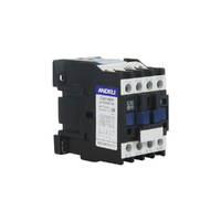
AC Contactors
AC contactors are the most common type, designed for alternating current circuits. The AC coil uses a shading ring to prevent contact chatter at zero crossing points. These contactors handle the full spectrum of AC loads from lighting to motors. They operate reliably with standard three-phase power distribution systems.
DC Contactors
DC contactors switch direct current circuits, commonly found in renewable energy systems, battery banks, and DC motor drives. DC circuits present unique challenges because DC arcs are harder to extinguish than AC arcs. DC contactors use magnetic blowout coils and specialized arc chutes. The coil design differs from AC contactors, using permanent magnets or DC coils without shading rings.
Reversing Contactors
Reversing contactors change the direction of three-phase motors by swapping two phases. These assemblies combine two contactors with mechanical or electrical interlocking to prevent both contactors from closing simultaneously. Applications include conveyor systems, hoists, and automated gates where bidirectional motor control is required.
Vacuum and Solid-State Contactors
Vacuum contactors use sealed chambers where contacts operate in a vacuum environment. This design eliminates arc oxidation and extends contact life in demanding applications. Solid-state contactors use power semiconductors instead of mechanical contacts. These devices offer silent operation, no mechanical wear, and precise switching control. They work well in applications requiring soft starting or where mechanical vibration must be avoided.
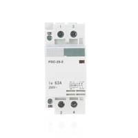
Single Phase vs Three Phase Contactors
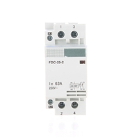
Power Capacity and Load Applications
Single-phase contactors switch one or two poles and handle loads up to around 63 amps in residential and light commercial settings. Common applications include pool pumps, air conditioners, and lighting circuits. Three-phase contactors use three or four poles to switch all phases simultaneously. This configuration is essential for balanced three-phase loads and motor control.
Residential vs Industrial Use Cases
Residential applications rarely require three-phase power. Single-phase contactors adequately serve domestic needs. Industrial facilities operate primarily on three-phase power for efficiency and motor performance. A 415V three-phase motor draws less current per phase than an equivalent single-phase motor, allowing smaller conductors and electrical switches.
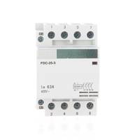
Selecting the Correct Phase Configuration
Count the number of load conductors. A single-phase load uses two or three conductors (line, neutral, and possibly earth). A three-phase load uses three or four conductors (three phases and possibly neutral). Match the contactor pole count to the load. Three-phase motors always require three-pole or four-pole contactors. Never use single-phase contactors on three-phase circuits.
Understanding Contactor Ratings and Sizes
Current Ratings and Power Capacity
Contactor thermal current (Ith) indicates continuous current carrying capacity. AC-1 and AC-3 ratings specify switching capacity under different load types. AC-1 applies to resistive loads like heaters. AC-3 applies to motor loads with high inrush current. A contactor might carry 40 amps continuously but only switch 25 amps of motor load.
Understanding AC-3 Motor Ratings
AC-3 ratings account for motor starting current, which can reach 6-8 times full load current. Always verify the AC-3 rating matches or exceeds the motor full load current. Using AC-1 ratings for motors will lead to premature contact failure.
Common Sizes (Size 0, Size 1, Size 2 and Above)
IEC contactor sizes follow a standardised numbering system. Size 0 handles motors up to 9kW at 415V. Size 1 extends to 15kW. Size 2 covers 18.5-22kW. Larger sizes continue up to Size 7 for motors exceeding 400kW. North American NEMA sizes follow a similar progression with different power ratings.
Matching Contactors to Motor Loads and Circuits
Calculate motor full load current from nameplate data or standard tables. Select a contactor with an AC-3 rating 25-30 percent above the motor full load current. This margin accounts for voltage fluctuations and provides a safety factor. For frequent starting applications, increase the margin to 50 percent. Coordinate with changeover switches when dual supply systems are present.
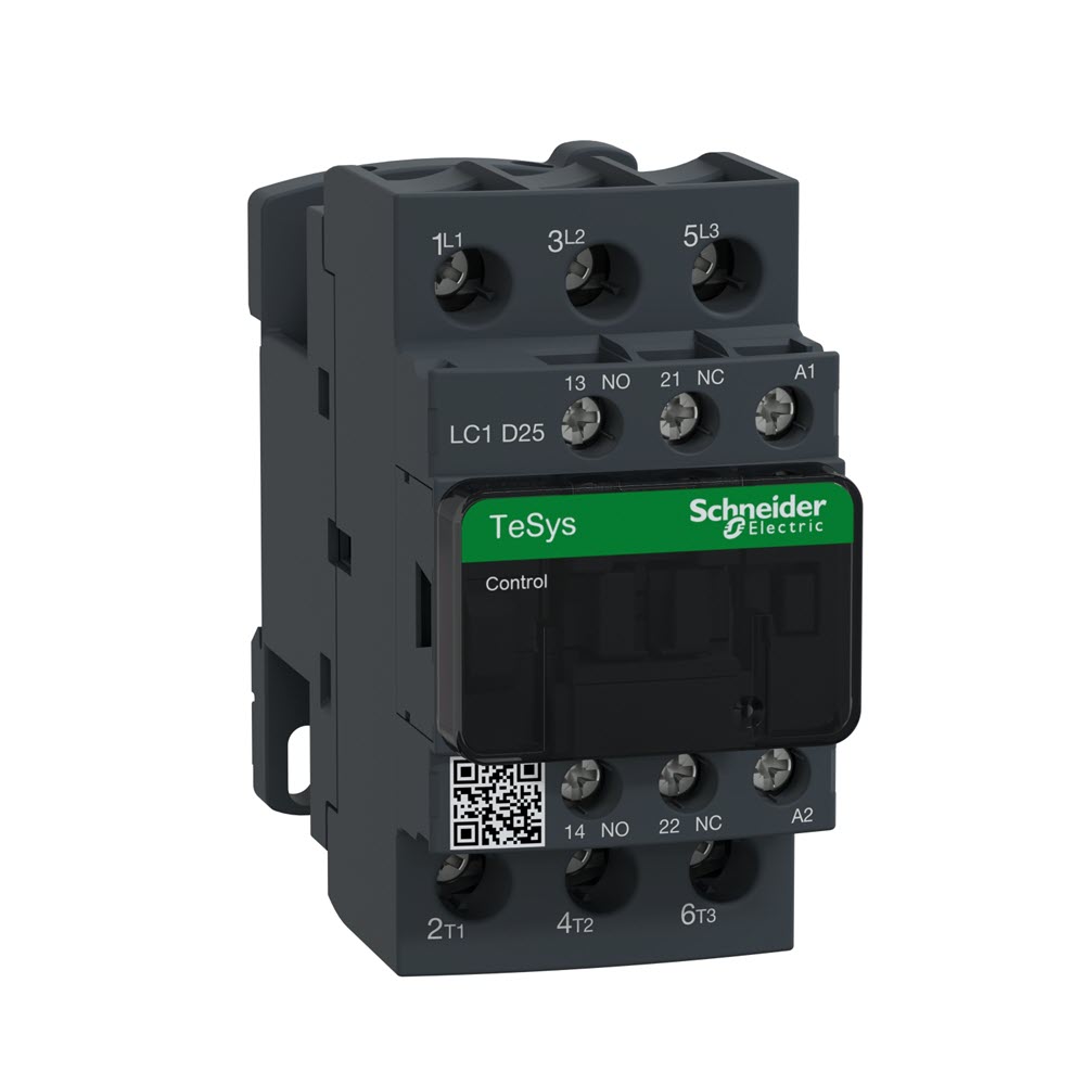
Main Components of an Electrical Contactor
Electromagnetic Coil Operation
The coil assembly consists of copper wire wound around a laminated iron core. The number of turns and wire gauge determine coil voltage and current requirements. AC coils include a shading ring, a copper or aluminum band that creates a phase shift in the magnetic field. This shift prevents the armature from buzzing at twice the line frequency. DC coils omit the shading ring and require steady DC voltage.
Armature and Main Contacts
The armature is the moving part of the magnetic circuit. Spring pressure holds it in the open position when the coil is de-energised. When energised, the electromagnetic field pulls the armature against the fixed core. The main contacts attach to the armature assembly. As the armature moves, it carries the moving contacts into contact with the fixed contacts. Contact pressure comes from spring loading designed to minimise contact resistance and prevent bouncing.
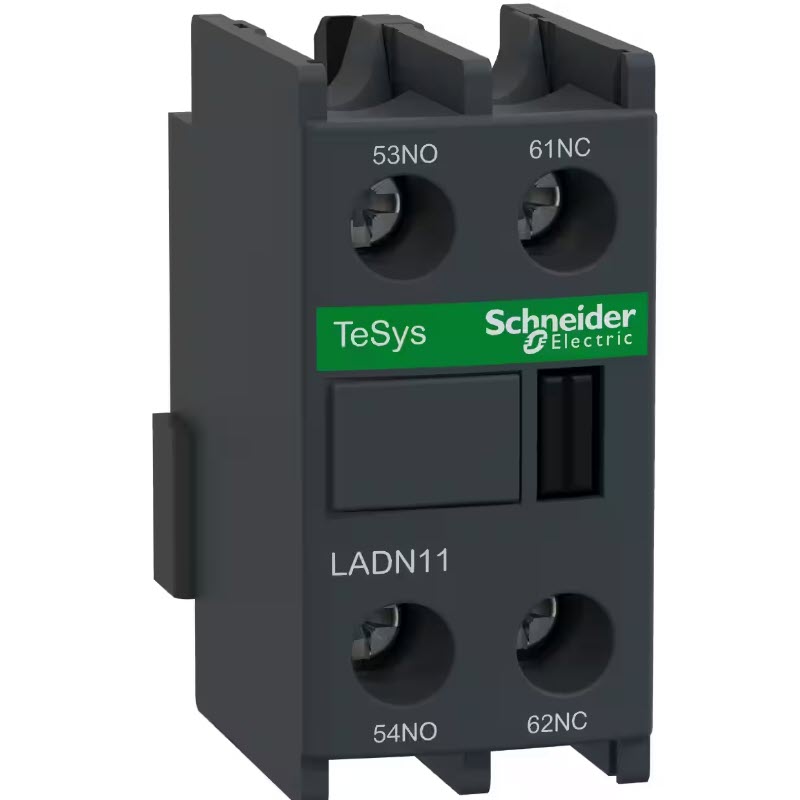
Auxiliary Contacts and Mechanical Linkages
Auxiliary contacts mount on the same armature assembly. They operate simultaneously with the main contacts but handle only control current. These contacts signal the contactor state to indicators, timers, and interlock circuits. Mechanical linkages ensure all contacts operate in unison. Clipsal and other manufacturers offer modular auxiliary contact blocks that snap onto standard contactor frames.
Coil Voltage and Control Circuit Considerations
Common Coil Voltages (24V, 110V, 230V, 415V)
Low voltage coils (24V) are common in industrial control systems using programmable logic controllers. These systems use transformer-isolated 24V DC supplies for safety and noise immunity. 110V coils suit North American control circuits. 230V coils match Australian single-phase voltage standards. 415V coils are less common but eliminate the need for control transformers in direct-on-line starters.
Choosing the Correct Control Voltage
Match coil voltage to your existing control system. If building a new panel, 230V AC simplifies wiring in Australian installations. For complex automation systems, 24V DC offers better integration with PLCs and safety relays. Never operate a contactor at voltages below 85 percent of rated coil voltage. Undervoltage causes weak magnetic force, leading to contact bounce and arcing.
Coil Response Time and Performance
AC contactors close in 50-80 milliseconds. DC contactors respond faster, typically 20-40 milliseconds. Coil protection devices include snubber circuits to suppress voltage spikes when the coil de-energises. These spikes can damage sensitive control equipment. Surge suppressors across the coil terminals protect connected electronics and extend coil life.
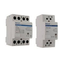
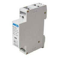
DIN Rail Contactors and Modular Systems
DIN Rail Mounted Contactors Explained
DIN rail mounting standardises electrical component installation in control panels and distribution boards. The contactor snaps onto a 35mm rail, requiring no drilling or fixed mounting. This system speeds installation and allows easy reconfiguration. DIN rail contactors suit applications where panel space is limited and multiple devices need organised mounting.
Modular Installation Advantages
Modular contactors accept plug-in auxiliary contact blocks, timers, and surge suppressors. Build up the contactor assembly to match application requirements without replacing the base unit. Change components in the field without extensive rewiring. This flexibility reduces inventory costs since one base contactor serves multiple configurations.
Applications in Smart Buildings and Distribution Systems
Modern building management systems use DIN rail contactors integrated with circuit protection components. These compact installations fit within electrical risers and subdistribution boards. Communication modules add contactor status monitoring to building automation networks. This integration supports energy management, scheduled lighting control, and remote fault diagnosis.
Contactors for Motor Control Applications
Pumps, Compressors, and Conveyor Systems
Pump motors operate for extended periods with infrequent starting. Select contactors rated for the motor power and ensure adequate ventilation to dissipate coil heat. Compressor motors impose demanding starting conditions due to residual system pressure. Use contactors with high AC-3 ratings and consider delayed restart timers. Conveyor systems require frequent reversing. Reversing contactors with mechanical interlocking prevent phase-to-phase faults.
HVAC and Air Conditioning Systems
Air conditioning compressor contactors must handle locked rotor current during startup. Single-phase compressors up to 5 horsepower use definite purpose contactors designed for HVAC loads. These contactors include silver-cadmium-oxide contacts that resist welding under inrush conditions. Three-phase HVAC systems use standard motor contactors sized for the compressor full load current plus safety margin.
Integration With Overload Relays and VSDs
Mount thermal overload relays directly to contactor terminals. This compact assembly simplifies wiring and reduces panel space. Set the overload trip current to 110-115 percent of motor full load current. When using variable speed drives, the contactor operates as an isolation device rather than a switching device. Place the contactor on the supply side of the drive to enable safe disconnection during maintenance. Coordination with Siemens drives requires careful attention to switching sequences.
Contactors for Lighting and Power Distribution
Lighting Control in Commercial Buildings
Contactors switch banks of fluorescent or LED lighting in warehouses, office buildings, and retail spaces. AC-1 rated contactors handle these resistive loads easily. LED lighting presents low inrush current, allowing smaller contactors than tungsten or fluorescent loads. Modern lighting contactors integrate with occupancy sensors and daylight harvesting systems. Time clock control enables scheduled on-off cycles for energy management.
Load Shedding and Demand Management
Demand management systems use contactors to disconnect non-essential loads during peak pricing periods. Priority-based schemes shed loads in sequence as power demand rises. HVAC, water heating, and lighting circuits disconnect in a programmed order. This automated shedding prevents demand charges and reduces energy costs. Restore circuits automatically when demand falls below the threshold.
Automated Power Switching Applications
Dual supply systems use contactors with mechanical or electrical interlocking to switch between mains and generator power. Four-pole contactors ensure complete isolation of the inactive source. Changeover switches coordinate with contactors to provide manual override capability. Automated transfer schemes monitor supply voltage and frequency, transferring loads within seconds of detecting a fault.
Choosing the Right Electrical Contactor
Matching Current Rating to Load Type
Identify the load type first: motor, resistive heating, capacitive, or mixed. Motors require AC-3 ratings. Heaters use AC-1 ratings. Capacitor banks need contactors rated for capacitive switching. Mixed loads require the most demanding rating in the circuit. Calculate load current accurately. Undersizing leads to contact welding and nuisance tripping. Oversizing increases cost without benefit.
Selecting Based on Duty Cycle and Switching Frequency
Light duty applications involve a few operations per day. Standard contactors serve these applications well. Medium duty extends to dozens of operations per hour. Heavy duty applications perform hundreds or thousands of operations daily. Check the manufacturer endurance ratings. These specify expected contact life under various operating frequencies. High-frequency applications may justify solid-state contactors despite higher initial cost.
Environmental Considerations and Enclosure Protection
Standard contactors suit clean, dry indoor environments. Outdoor or wet locations require contactors in IP65 or higher enclosures. Corrosive atmospheres need stainless steel hardware and conformal coated coils. High ambient temperatures derate contactor current capacity. Manufacturers provide derating curves for temperatures above 40 degrees Celsius. Altitude derating applies above 1000 metres due to reduced air density affecting cooling and arc extinction.
Installation and Wiring Best Practices
DIN Rail and Panel Mounting
DIN rail mounting requires firm pressure until the contactor snaps into place. Verify the rail is straight and firmly secured. Panel-mounted contactors need four mounting screws and lock washers. Leave adequate clearance above and below for cooling airflow. Allow at least 50mm spacing between adjacent contactors. Mount contactors vertically to promote proper arc venting.
Wiring Main and Control Circuits Correctly
Main circuit terminations require proper torque to ensure low contact resistance. Under-tightening causes overheating. Over-tightening damages terminals. Use a calibrated torque screwdriver or wrench. Strip cable insulation to the correct length to prevent exposed copper while avoiding excess wire inside the terminal. Control circuit wiring uses smaller conductors, typically 1-1.5mm2. Label all control wires clearly. Separate control and power wiring to reduce electrical noise coupling.
Safety Requirement: All contactor installations must comply with AS/NZS 3000 wiring rules. The supply must be isolated and locked out before commencing work. Verify all circuits are de-energised with an approved voltage tester. Only licensed electricians may perform contactor installations connected to mains power.
Safety Interlocking and Protection Requirements
Mechanical interlocking prevents simultaneous operation of conflicting contactors in reversing or changeover applications. Install auxiliary contacts to signal contactor state to the control system. Add surge suppressors across inductive loads to protect contactors and control equipment. Fuse or circuit breaker protection on the supply side prevents damage from downstream faults. Coordinate protection devices with contactor short-circuit withstand ratings.
Common Installation Mistakes to Avoid
Undersized Contactors for Motor Loads
Specifying contactors based on AC-1 ratings instead of AC-3 ratings leads to rapid contact failure. Motor starting current creates severe arcing that quickly erodes undersized contacts. The contactor may operate initially but fails within weeks or months. Always verify AC-3 ratings match motor full load current with appropriate safety margin.
Incorrect Coil Voltage Selection
Applying 415V to a 230V coil destroys the coil winding immediately. Operating a 230V coil on 110V results in weak pull-in force and contact chatter. Coil voltage must match control circuit voltage precisely. When replacing contactors, verify coil voltage markings. Never assume the new contactor matches the old one without checking specifications.
Poor Ventilation and Heat Management
Enclosing contactors in sealed boxes without ventilation causes coil overheating and reduces contact life. Coils generate significant heat during operation. High ambient temperatures compound the problem. Provide adequate ventilation openings in enclosures. Use forced air cooling in high-temperature environments. Space contactors to allow natural convection airflow. Monitor enclosure temperatures during operation.
Contactor Maintenance and Lifecycle Management
Inspecting Contacts for Wear and Arcing
Schedule annual inspections for contactors in critical services. Bi-annual or quarterly inspections suit high-duty applications. Isolate and lock out the circuit before opening the contactor. Examine contacts for pitting, erosion, and discolouration. Light pitting is acceptable. Deep erosion indicates end of contact life. Measure contact resistance if testing equipment is available. Rising resistance indicates degradation even when contacts appear serviceable.
Coil Resistance Testing and Diagnostics
Measure coil resistance with the contactor de-energised and disconnected from the circuit. Compare measured resistance to manufacturer specifications. Resistance significantly lower than specified indicates shorted turns. Higher resistance suggests corrosion or poor connections. Test coil pull-in voltage by gradually increasing supply voltage while monitoring armature movement. Pull-in should occur between 85-90 percent of rated voltage.
Replacing Contacts and Refurbishment Kits
Many contactor manufacturers offer contact replacement kits. These kits include main contacts, springs, and sometimes arc chutes. Replacing contacts costs 30-50 percent of a new contactor. The refurbishment extends contactor life by several years. Follow manufacturer procedures exactly. Incorrect assembly causes misalignment and premature failure. Some applications justify complete replacement rather than refurbishment, particularly when labour costs are high.
Troubleshooting Common Contactor Problems
Contactor Not Pulling In
Verify control circuit voltage at the coil terminals. Voltage should match coil rating during energisation. Low voltage indicates supply problems or excessive circuit resistance. Check for blown fuses or tripped breakers in the control circuit. Inspect control circuit wiring for loose connections. If voltage is correct and the contactor still fails to close, the coil may be open circuit or the mechanical assembly may be jammed.
Contacts Welding or Sticking
Welded contacts indicate excessive switching current or voltage. Verify the load matches contactor ratings. Short circuit faults cause instantaneous welding. Install proper upstream protection to prevent short circuits from reaching the contactor. Oversized loads cause gradual welding through repeated arcing. Reduce load or upsize contactor. Capacitive loads generate high inrush current that welds contacts. Add series inductors to limit inrush.
Intermittent Operation and Coil Failure
Chattering contactors indicate undervoltage conditions or mechanical problems. Check control circuit voltage under load. Voltage drop in long control circuit runs causes chattering. Increase wire size or relocate control transformer closer to the contactor. Rapid contact cycling generates excessive heat that damages coils. Install timers to enforce minimum off periods between starts. Failed coils usually show discolouration or burning smells. Replace failed coils or the complete contactor depending on cost considerations.
Advances in Contactor Technology
Solid-State and Hybrid Contactors
Solid-state contactors use thyristors or power transistors instead of mechanical contacts. These devices offer unlimited switching life and precise zero-crossing switching. They operate silently without mechanical wear or bounce. Applications include soft motor starting, dimming control, and high-frequency switching. Limitations include higher cost, heat generation requiring heatsinks, and potential failures from voltage transients.
IoT and Smart Monitoring Features
Modern contactors integrate communication modules that report status, switching cycles, and contact condition to building management systems. Predictive maintenance algorithms analyse switching patterns to forecast contact wear. Cloud connectivity enables remote monitoring of distributed installations. Energy monitoring built into smart contactors tracks load current and power consumption. This data supports energy management and billing systems.
Integration With PLCs and Automation Systems
Direct communication between contactors and programmable logic controllers eliminates separate relay interfaces. Industrial network protocols such as Profibus, Modbus, and EtherNet/IP enable sophisticated control schemes. Distributed I/O modules place contactors close to loads while maintaining centralised control. This architecture reduces wiring complexity in large facilities. Safety-rated contactors integrate with emergency stop circuits using certified safety protocols.
Compliance and Australian Standards
AS/NZS 3000 Wiring Rules
AS/NZS 3000 specifies installation requirements for electrical equipment in Australia and New Zealand. Section 2 covers protection against electric shock. Contactors must be installed in enclosures that prevent accidental contact with live parts. Section 3 addresses protection against overcurrent. Upstream protection devices must coordinate with contactor ratings. Section 4 covers earthing. All contactor frames and enclosures require earth connections.
Product Standards and Certification Requirements
IEC 60947-4-1 specifies contactor design and testing requirements. This international standard covers ratings, mechanical endurance, and electrical endurance testing. Products marketed in Australia should display compliance marks indicating certification to Australian standards. Eaton and other major manufacturers certify their products to these standards.
Safe Installation by Licensed Electricians
Only licensed electricians with appropriate qualifications may install contactors connected to fixed electrical installations. Electrical work performed by unlicensed persons breaches state and territory electrical safety regulations. Licensed electricians understand protection coordination, circuit design, and testing requirements. They carry appropriate insurance coverage. DIY installations of contactor circuits pose electrocution and fire risks. Hire licensed professionals for all contactor installations.
Buying Electrical Contactors in Australia
Where to Buy Online
Online electrical wholesalers stock extensive contactor ranges at competitive prices. Sparky Direct offers brands including Schneider, Eaton, Siemens, and Clipsal. Online shopping provides detailed product specifications, datasheets, and wiring diagrams. Filter products by current rating, coil voltage, and mounting type. Compare prices across models to optimise value. Express shipping ensures quick delivery to metro and regional locations across Australia.
Cheap vs Trade-Grade Options
Budget contactors suit non-critical applications with infrequent switching. These units meet basic performance requirements at lower cost. Trade-grade contactors from established manufacturers offer proven reliability and local technical support. Higher initial cost delivers better value through extended service life and reduced maintenance. Critical applications such as fire pumps, emergency power, and production equipment justify premium contactors. Non-essential loads accept budget options where downtime is tolerable.
Bulk Purchasing for Contractors and OEMs
Regular contactor users benefit from volume purchasing agreements. Bulk pricing reduces per-unit costs significantly. Maintain inventory of common sizes to avoid project delays. Original equipment manufacturers integrate contactors into control panels and machines. Establish preferred supplier relationships to ensure consistent product availability. Standardise on specific brands and models to simplify spare parts inventory. Request technical support and application assistance from suppliers during product selection.
Product Videos
Watch Clipsal Iconic 40MLEDW Switch Mechanism video
Watch Clipsal Iconic 40MLEDW LED Module installation video
Watch Clipsal Iconic 40MLEDW features and specifications video
What Sparky Direct Customers Say

In the world of electrical systems, reliability and seamless transitions are paramount. The HAGER SF463 Changeover Switch, a 4 Pole 63 Amp marvel, stands as a testament to precision engineering and top-tier functionality. This switch has not only met but exceeded expectations in every aspect of its design and performance. The 4-pole configuration of the HAGER SF463 ensures a robust and comprehensive electrical setup. Whether it's for industrial applications or demanding commercial installations, this changeover switch proves its mettle. The 63 Amp capacity adds a layer of versatility, accommodating a wide range of electrical loads with ease.
Sparky Direct literally saved my Christmas display. We had used all of the metal clips from previous years, and still had 50 metres of rope lights still to go up. So I frantically searched the internet to find clips that suited my application and was very pleased to find that Sparky Direct had exactly what I needed in stock. I placed my order online on Saturday, and my parcel was delivered on Tuesday. All was looking good until I went to open the packet and discovered the clips required a tool to close them. No problem I thought, I've been doing electrical work for over 45 years, so naturally I should have the required tool. Unfortunately this was not the case, and with Christmas fast approaching, I again searched Sparky Direct's website for an emergency solution and found crimping pliers. Placed the order Saturday, received parcel Tuesday.
I recently installed the Clipsal 750WPR5-GY Infrascan PIR Sensor in a outdoor area, and I'm thoroughly impressed with its performance. Right out of the box, the installation was straightforward, thanks to the clear instructions and user-friendly design. The sensor's 18m detection range is exceptional, covering a broad area and providing reliable motion detection even in challenging outdoor conditions. One of the standout features of this PIR sensor is its sensitivity and responsiveness. It accurately detects motion and triggers the connected lighting system promptly, which significantly enhances security and convenience. The grey finish is subtle and blends well with the outdoor environment, maintaining a clean aesthetic without drawing unnecessary attention.
- Electrical contactors are heavy-duty electromagnetic switches designed for high-power industrial and commercial applications, enabling safe remote control of motors, lighting, and distribution circuits
- Contactors differ from relays in power handling capacity: contactors manage 10-400+ amps while relays typically handle under 15 amps, with contactors built specifically for frequent switching and motor starting duty
- AC-3 ratings are critical for motor applications as they account for high inrush currents during starting, while AC-1 ratings apply to resistive loads like heaters and lighting circuits
- Three-phase contactors require three or four poles to switch all phases simultaneously, essential for balanced industrial motor loads, while single-phase contactors suit residential and light commercial applications
- DIN rail mounting enables modular installation with auxiliary contacts, timers, and communication modules that adapt contactors for building automation and smart control systems
- Proper installation requires matching coil voltage to control circuits, torque specifications for terminals, adequate ventilation, and compliance with AS/NZS 3000 wiring rules by licensed electricians
Shop Electrical Contactors at Sparky Direct
Trusted brands • Expert advice • Fast Australia-wide delivery • Trade pricing
Shop Electrical Contactors → Get Expert Advice →Electrical Contactors Frequently Asked Questions
Do electrical contactors improve system reliability?
Yes, they are designed for frequent switching and long service life.
Electrical Contactors near me
Sparky Direct supplies electrical contactors Australia-wide, offering quality control solutions with convenient delivery.
How are electrical contactors delivered?
Electrical contactors are securely packaged and delivered via standard courier services.
Can unused electrical contactors be returned?
Unused products are generally eligible for return according to the seller’s returns policy.
What warranty applies to electrical contactors?
Warranty coverage varies by manufacturer and typically covers defects in materials or workmanship.
Are electrical contactors sold individually?
Yes, electrical contactors are typically sold as individual control components.
Should contactor selection be planned carefully?
Yes, correct sizing and specification are essential for safe and reliable operation.
Do electrical contactors require regular maintenance?
They generally require minimal maintenance when correctly specified and installed.
Are electrical contactors suitable for continuous operation?
They are designed to handle frequent and continuous switching within their ratings.
Do electrical contactors make automation possible?
Yes, they play a key role in automated control systems.
Are electrical contactors used in HVAC systems?
Yes, they are commonly used to control air conditioning and heating equipment.
Are electrical contactors durable?
Quality contactors are built to withstand repeated operation under load.
Are electrical contactors easy to identify in a control panel?
Yes, they are typically clearly labelled and mounted on DIN rail or panels.
What is an electrical contactor?
An electrical contactor is a control device used to switch electrical circuits on and off, typically for higher current loads.
Are electrical contactors commonly used by electricians?
Yes, they are a standard component in many electrical installations.
Why are electrical contactors important?
They allow safe and reliable control of high-power electrical equipment.
Can electrical contactors be used with control panels?
Yes, they are a standard component in electrical control panels.
Are electrical contactors suitable for motor control?
Yes, they are commonly used for starting and stopping electric motors.
Are electrical contactors available in different current ratings?
Yes, they are available in a wide range of current ratings to suit different loads.
What voltage coils are available for electrical contactors?
Contactors are available with various coil voltages depending on control circuit requirements.
Can electrical contactors be used in commercial buildings?
Yes, they are commonly used in HVAC systems, lighting control, and machinery.
Are electrical contactors used in industrial applications?
Yes, they are widely used in industrial and commercial electrical systems.
Do electrical contactors comply with Australian standards?
Quality electrical contactors are manufactured to meet relevant AS/NZS electrical and safety standards when installed correctly.
How is a contactor different from a relay?
Contactors are designed for higher current and voltage applications, while relays are generally used for lower loads.
What are electrical contactors used for?
They are used to control motors, lighting circuits, heating systems, and other electrical equipment.